KSS loosely dropped together on the bench
Or a bunch of rather butchered bits
How photos can lie!! Just look at this picture above, for example! Looks magnificent! The start of a superb new project, almost finished, even!! WRONG!
And so the voyage of discovery goes on. Only trying to turn the engine by the crankshaft damper (no clutch or chain) and with the valve covers off (no screws anyway!) I noticed that I could turn the engine full circle without actuating a valve! This was either a Velocette patent to reduce the cost of fuel, or…there was something very wrong here. On a 70 year-old Overhead-camshaft engine, very wrong translates almost directly into any language as very expensive.
For this section, I shall limit my attention the subject of the valve-actuating mechanism…I then decided to take a look at the bottom end, at the end of the crankshaft in this case.
I digress: This is standard procedure for any fault finding, you have to start at the end where you believe that things begin to work and work your way through to where they stop working! Most starting problems, or a sudden refusal to go, if not accompanied by a ‘BANG!’, can generally be put down to one of two things (having ‘eliminated’ mechanical failure at this juncture): No fuel or no spark. Easiest to test is no spark. If the spark is good, we then go to fuel. If there is fuel getting through, then we have to ask (as fuel doesn’t depend on ‘timing, just ‘being there’ at this testing phase), we then have to look at the question is the spark at the right time etc, until we come to discover the reason for the failure (which in this case could still be a many things!)
Back to the mechanical problem at hand: If the crankshaft is turning (yes, the piston is going up and down, I can see through the hole) then at least the drive side is still attached to the big-end! To check if the timing-side is still ‘whole’, I have to take off the two timing covers, outer and inner. On removal of the outer chain-case, it could be seen that the sprocket was turning…good!
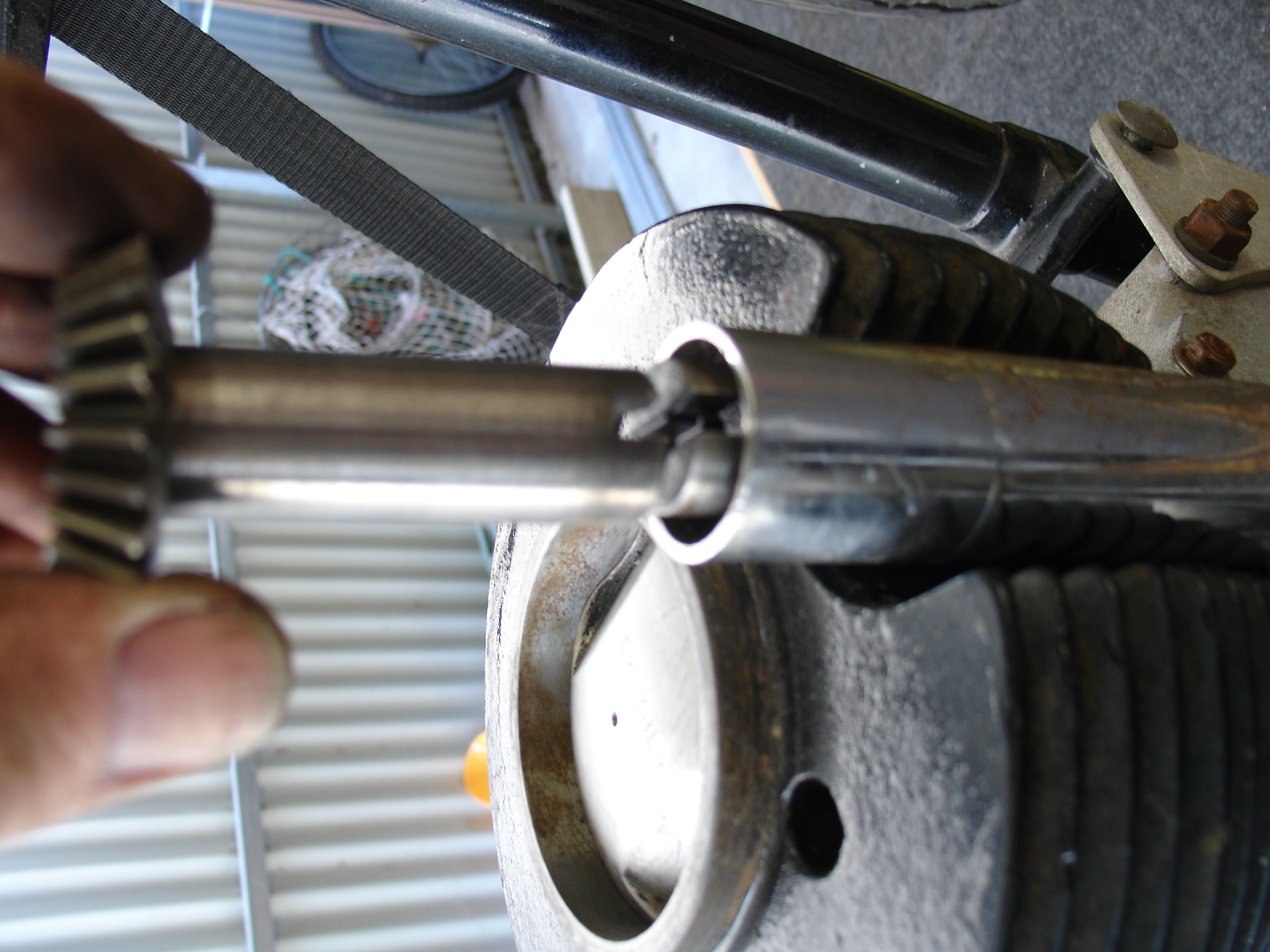
Now to the inner chain-case, where the oil-pump and the bevel-drive on the end of the crank-shaft is! All seems well here, thank God, and all the bits seem to be here, which is a blessing. So now I ‘know’ that something with the drive between the head and the base of the drive must be
missing or broken. This is driven by a shaft with a coupling at each end, as will be seen. The logical and easiest thing to do next is to take the head off, to get a peek at the inside of the drive-shaft ‘tunnel’.
The head came off far too easily, not being tightened down and ‘held’ in place only by the two bolts on the timing side…

KSS MkII Cylinder-head from drive side, pictured from above ‘waistline’

KSS MkII Cylinder-head viewed from underneath, showing drive slot in the gear-shaft

Cylinder, piston and OHC drive-shaft to head on KSS MkII

Driveshaft coupling on OHC drive of MkII KSS
KSS OHC Drive by bevel/shaft. The gap is where the missing coupling should go…
Not really surprising, that it didn’t work then, is it! I am
still not finished, though. If that’s missing, what else is not there, might be worth looking a bit further into things, while I’m here!
So, off comes the shaft and tube. The coupling on the bottom is there and the bearings down below seem OK, too, not too much end play and no slop at all. Phew!
Back up to the head. That bevel seemed a bit sloppy, that’s not right. NOT RIGHT! That is VERY sloppy…I took the housing off that holds the bearing in place and could then pull the vertical bevel-gear out of the head, without disturbing the (big one in the picture above) which is attached to the cam.

Hole broken through into the bush through excessive wear, causing alarming play!
OOPS! I don’t know if the picture shows it so well, but there are four holes through the length of the bush…through turning the bush (in a lathe and that very coarsely!) out too much (instead of reaming…), one of the holes has broken into the bearing surface over it’s full length (as can be seen here). On closer inspection, the whole thing was obviously hand made (Great! Keep yourself on the road!), very badly (not great, in this case, disastrous!) I measured 20thou or .6mm difference between bore and shaft, just a bit loose, don’t you think? Not the sort of discrepancy you would expect for the meshing of two precision bevels, perhaps? Don’t worry, it would only have lasted five minutes anyway, even if it was the right size…look how it was kept in the housing!

How NOT to tighten the fit of a very loose bush in its housing…
Raise a few bumps with a punch to make it tighter and glue it with red ‘Loctite’, that should hold forever, mate!!
When I saw that, I had to take a break, so before making myself a coffee, I replaced the inner cover and taped up the ‘ole in the bottom bush housing to stop the ingress of low-flying seagulls and such-like (trapdoor spiders, down here!) and went inside…

Drive all covered up for the moment. I’ve had enough for the day!
The sprocket on the bottom left is the one I talked about at the beginning, after I removed the outer cover. This is the one I was watching to see if it turned, when I turned the crankshaft, remember?
More tomorrow, I suspect!
©peter gouws 2012