Wheels within wheels…
Ever thought of spoking your own wheels up? Look at the cost of getting someone else to do it (not that difficult to find, most Bikeshops or Motocross-oriented dealers as well as some tyre-places can do it for you). Don’t forget, though, they are probably earning on the rim and spokes as well as the lacing-up job (their entitlement, after all, that’s presumably what they are in business for – and continue to be!).
You, on the other hand, may be able to source your own spokes, rims and nipples for anyway usually less than you will be charged for by your ‘spoker-upper’, but will have to come to some arrangement with SWMBO regarding where to do it. You don’t need any fancy gear, either, but you can spend up to a couple of hundred Dollars on a smart jig if you want… I went the more ‘conservative’ route.
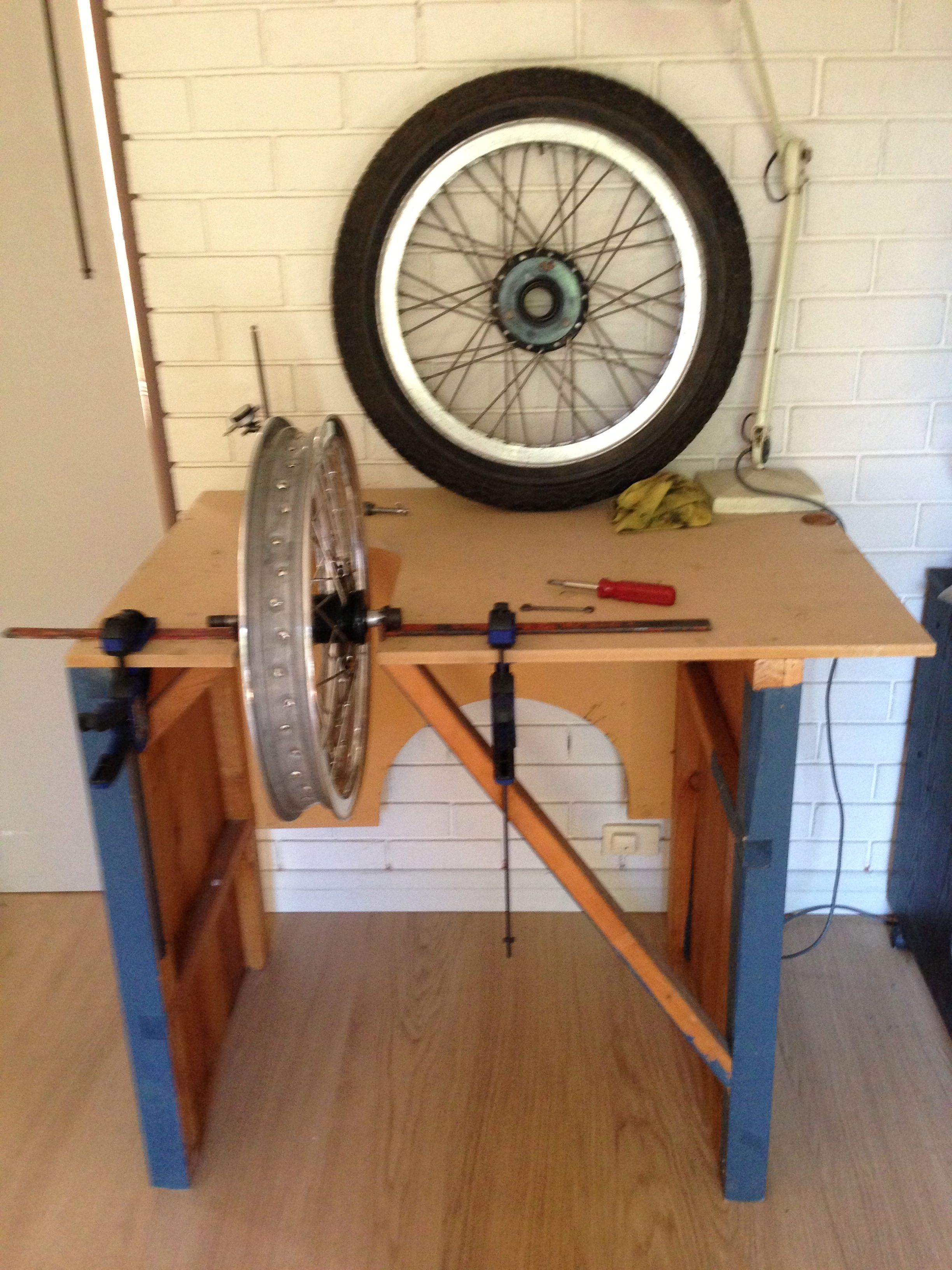
My brother, a jeweller amongst other things, was throwing out an old workbench he had provisionally made a few years ago and asked if I could use it. My immediate response was ‘no’, but on second thoughts, I did want to build a couple of wheels, so why not ‘modify’ the bench for that! Look at the picture above and you will see that the top was removed and recycled as a back to the bench (for stability… that’s one thing your jig should be, however you make it: you don’t want anything to wobble!
It stands 900mm high, which suits me fine at six foot, so I can sit or stand to work. I then made a new top from MDF that was lying about and cut a slot in it to make space for the wheel:

Notice the extra support at the front edges, to stop it ‘drooping’. The axle supports are also a bit of scrap I found with a “V” cut into them. Important is that a wheel can be supported on its axle in between them and that they are adjustable for distance apart from one another, to suit different axle widths. I simply drew a line across the bench along which the strips are aligned. they are fixed with clamps here, but you set up a fancy arrangement with slots and screws or wood-block or metal guides and screw-down-clamps or whatever you have or can get hold of.
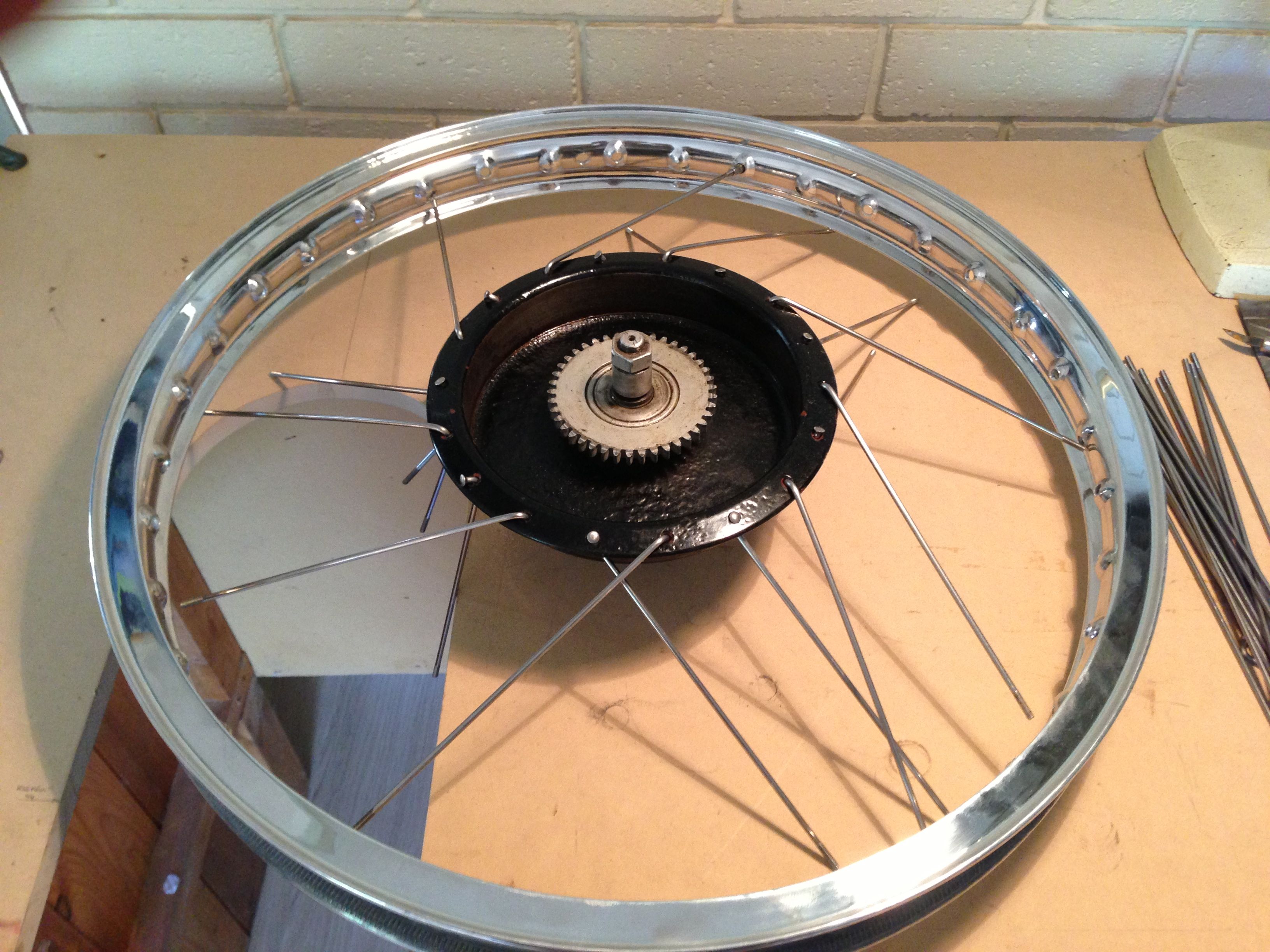
So, that’s the setup and this is what it looks like with a wheel resting in it:
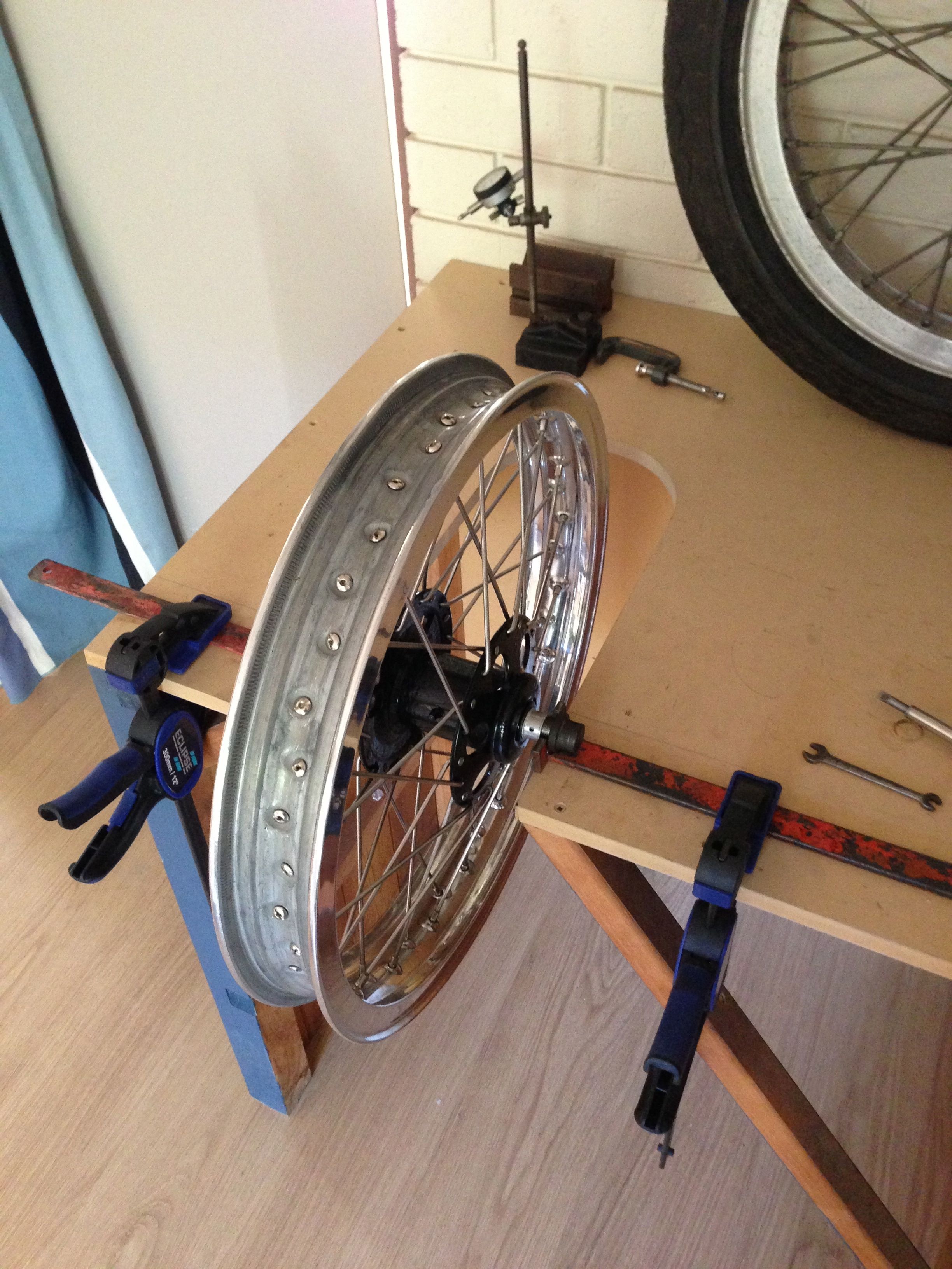
(actually a bit fast-forward, as in this picture the wheel is actually already finished!) You get the idea: It doesn’t have to be a vertical stand, you could use a singing arm, a rigid frame on end or girder forks held in a clamp etc…let your imagination run wild and your wallet needn’t suffer overly!
Now to get on with the actual spoking! I will, for the sake of simplicity, assume that you have already bought the correct rim, spokes and nipples that fit your hub and are ready to go!. Ah yes, a wide screwdriver will come in handy and the HEAD of a screw-bit and magnetic holder for an electric drill/screwdriver – more of that later… any extra clamps you feel necessary to hold the wheel-spindle in place (if necessary) and… a bit of time! I also expect that you know the offset of the rim from the hub, so that when built into your machine, the rim/tyre run on the centre-line, tucked neatly under your mudguard! If you don’t have numbers, maybe you have a sample wheel handy to copy and measure from (like I have in the pictures)
Some things are best done in sequences which can be broken up into smaller jobs, but should not be interrupted once started. That might mean a bit of concentration for ten or so minutes at a time, not much longer, so make a cuppa or get a glass/bottle of your favourite poison and let the lesson begin (self-taught)
You will notice that the bench is big enough to lay a 21” rim on with the hub in the middle (I could even fit a 23” Honda TL rim on it!) and I subsequently drilled a hole in the top to allow the front axle to go through, so that the hub-flange was on the surface and therefore ‘stable’
I always start at the valve-hole, since it’s always there! Whether 40- or 36-hole, the pattern is very similar and you will soon get into the routine of it. The front and the back were different not only in size: the rear hub is the same size left and right and the rim is laced on the centre-line of my sample, and the hub has holes in it for each spoke. The front has different diameters left and right ( due to the brake drum being one-sided and part of the hub, unlike the rear, where it simply bolts on) and this affects the drilling angles on the rim, so watch out! The brake-drum-side had holes around the rim and the nearside has double-keyhole-slots to accommodate the spokes, which at the same time make some things easier and other things more difficult…(spokes don’t fall out of holes, once they have been laced through, but they can and will fall out of slots, if you don’t follow a few simple ‘rules’)
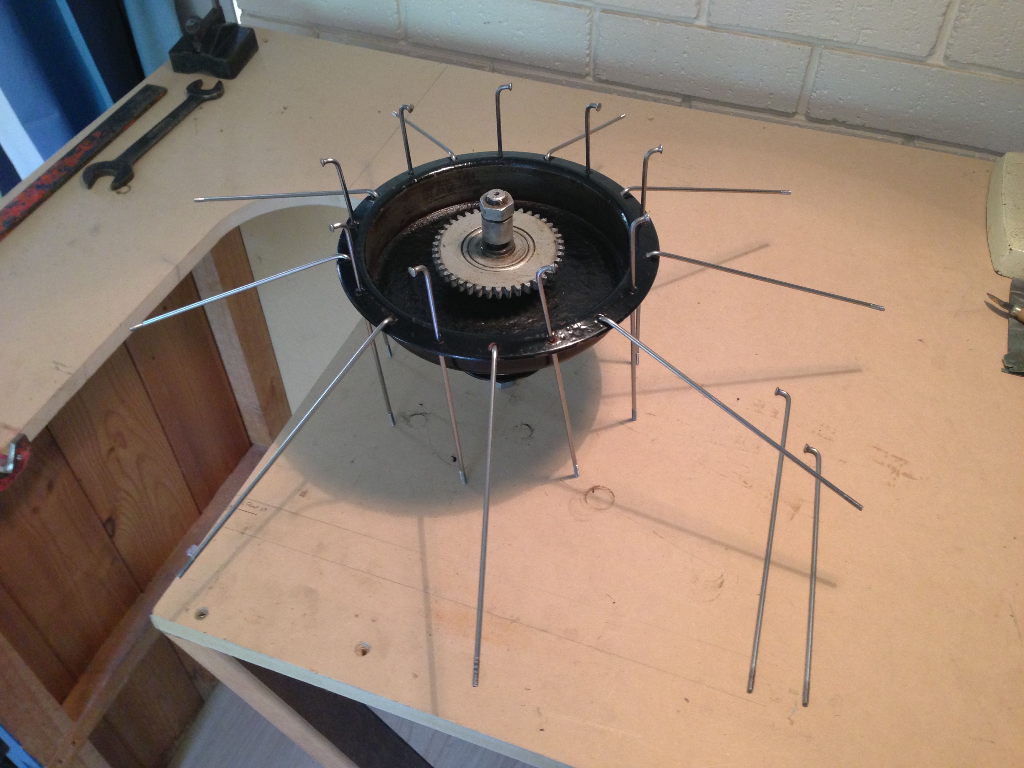
Get the hub and hold it in one hand. If it has holes in it, feed every other one with a spoke down through the holes and the ones in between, feed a spoke UP through the holes. If you are doing a rear wheel or one with holes on both sides, you have to this for both sides, before putting the wheel on the table. Otherwise you could put it down now, and pick it up the same way again later to do the other (top side), assuming that you started on the bottom-most ring of holes, as I always do for some reason.
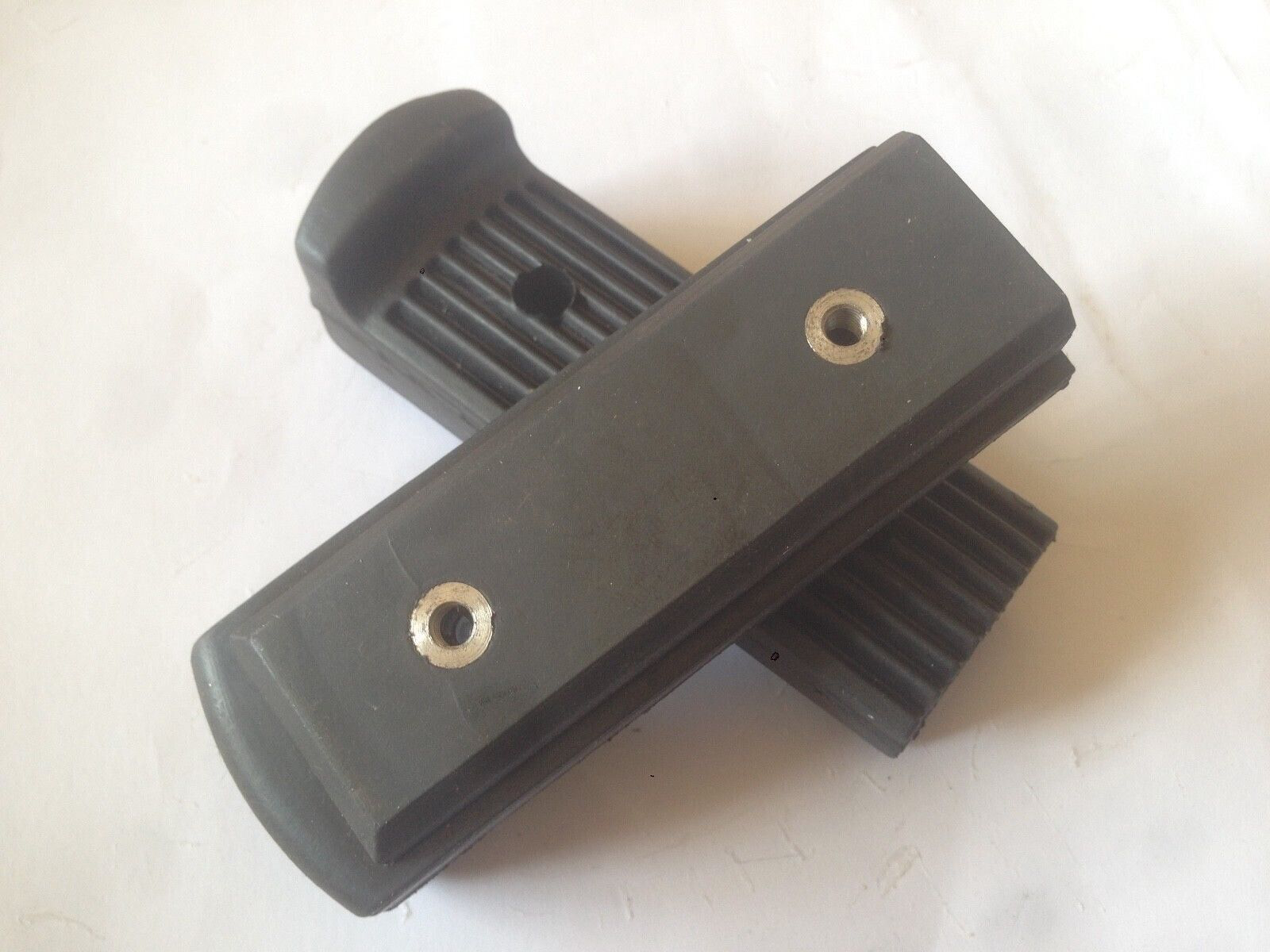
The picture shows a front hub, with a single-sided brake for girders on the Velocette (this is a slightly earlier hub than 1947 for those with sharp eyes, the ’47 hub is a casting!). The rear was impossible to hold and photograph at the same time! (after this is when I drilled the hole in the bench for the axle, so that the hub sat on the surface of the table, as in the following pics)
On the right you can see the different spoke-lengths for brake and non-brake-side of the hub. So, up, down, up, down all the way round. Since the other side has slots, I don’t need to put the spokes in there yet, (if you had a hub just with holes you would) so I just lay the hub on the table and placed the rim around it and started putting spokes in:
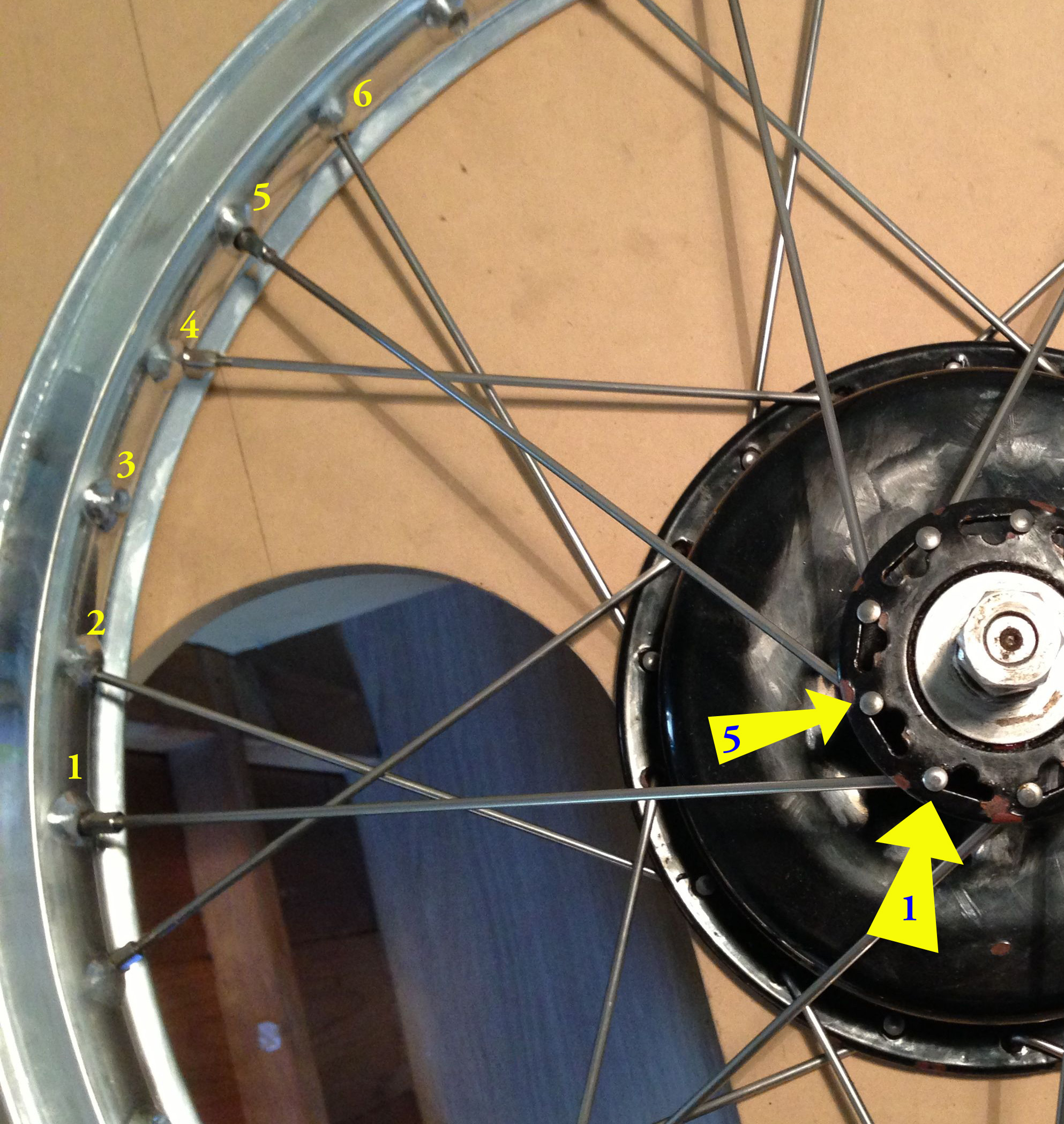
OK, spoke 1! I said to start at the valve, this I did, taking the first hole (drilling) clockwise, that pointed at the TOPSIDE of the brake-hub and BACK. This is super-critical, to get the first spoke set. Once in the hole on the rim, get a nipple and turn it on to the spoke only a couple of turns, just enough to stop it coming off at this stage.
Now, moving clockwise ( most caucasians do – it has to to with reading and writing from left-to-right, not if you are left- or right-handed) count four holes and put the NEXT SPOKE ON THE SAME SIDE ( top or bottom, up or down) in that hole, which should also conveniently point at where it’s coming from! If not, that’s a dead give-away that things are not right. Have another look, compare etc. In this case, there is a gap of three in between, or the next hole ‘looking in the same direction’ is the fourth along:

And so it goes on, until you have all the spokes that you threaded upwards (or downwards) in their respective ‘oles.
The other spokes, go in the OTHER direction, crossing over the spokes already fitted loosely. Please compare with your pattern/drawing, but often the NEXT ONE CLOCKWISE on the hub (on the ‘IN’ side in this case) will go SIX holes BACK (anti clockwise) from the ones on the TOP. Sounds complicated, but is actually simple. Look at the photo closer and all will be revealed!
What I have actually done is to turn the hub and wheel over after putting in all the spokes on the one side and have now fitted the one row of spokes going clockwise on the now upper, nearside of the hub. Just have alook and you will see what I meant in the last paragraph.
As ever, you will hopefully find that the drillings all point in the right direction… No power-maths required here: You will find that the spokes fit in the middle of the spaces between the spokes already set, so easy to do, leaving a hole each side, foe other side when you turn the wheel over! EASY! (SEE?!)
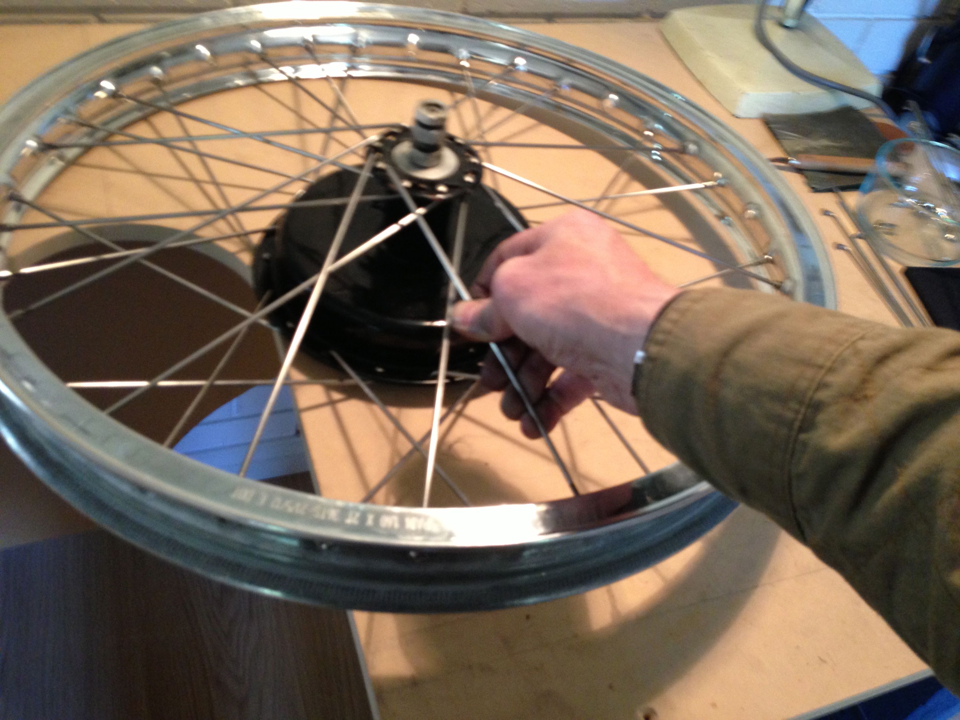
Here is the picture panned out a bit, showing the general arrangement. One row of spokes has been put in the slots, as can be seen. Slots are a bit easier, inasmuch as the spokes don’t all to have been fed into the hub from the start. Can be a pain, though as they can ‘constantly’ fall out. You can use a trick that I use: I put the nipple on the spoke a few turns BEFORE putting it in the wheel! HEH?
You can feed it in the RIM-hole, like this:
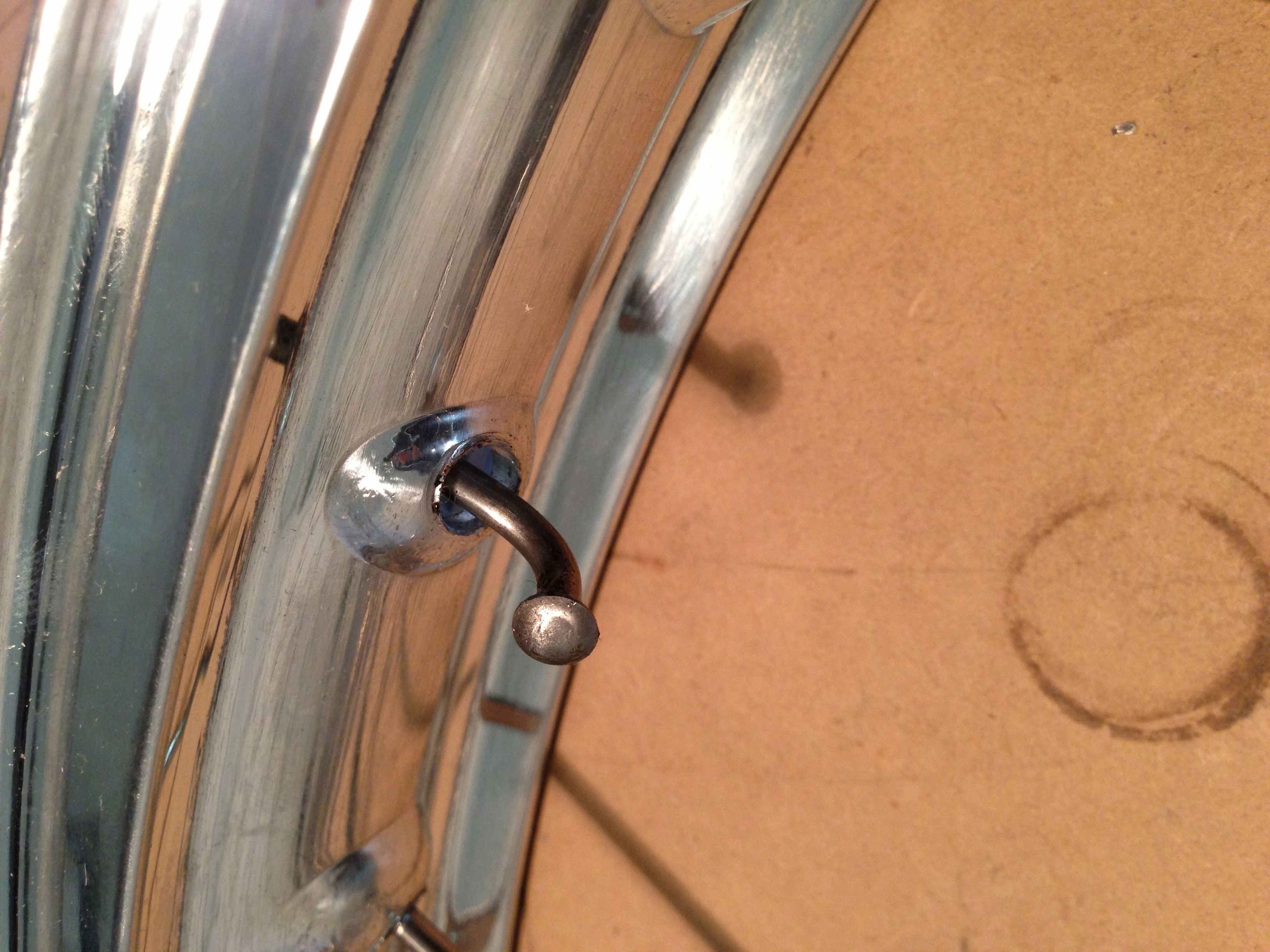
… And THEN into the slots…

This is easier if you tip the rim towards the hub, to bring the end of the spoke to go through the hole, letting the rim then fall back with gravity, to hold the spoke in the ‘slot’ part of the hole and not fall out!
Trueing? That’s a different story, and will follow on the next installment: Don’t forget, the welded join can be a bit problematical on these type of alloy rims and is nearly always a little out of line, but this wheel is true to 0.3 of a millimetre in all directions, that’s not much more than ten thou out… not unreasonable, really…
©peter gouws 2012