Prewar gearbox
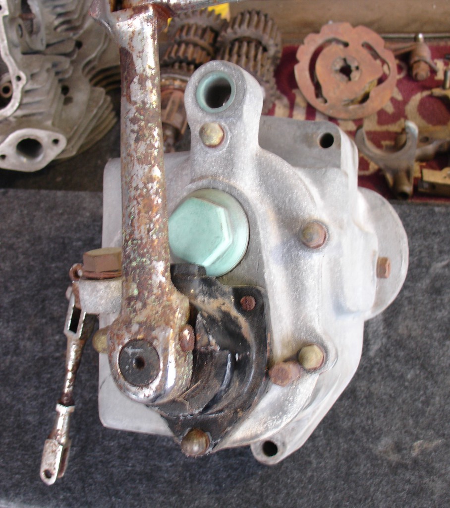
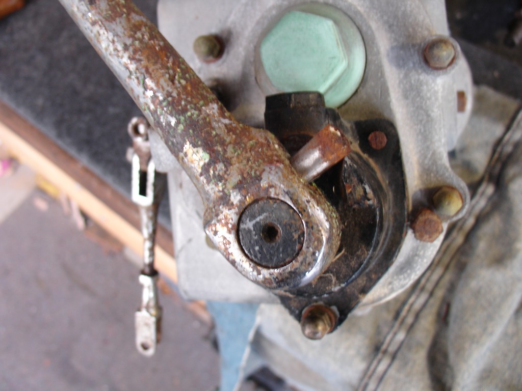
Well, this one looks like it might be slightly more complete and slightly more ‘oil’-tight. The kick-tarter is in the usual horrendous state! I don’t know why it is, but Velocette kickstart-levers are nearly always rusted-to-…well…buggery! First thing, then, is to get the lever off! First, I have to ‘depress’ the lever about 20° to allow the cotter-pin to be drifted out after the nut has been taken off, otherwise all I would be doing is smacking it against the ramp on the casting: Ping, ping, ping! (duh, done that before…)
Next I take that rather attractive green, brass, cover off the bearing on the end of the layshaft. AH, it looks almost new! This is goood!
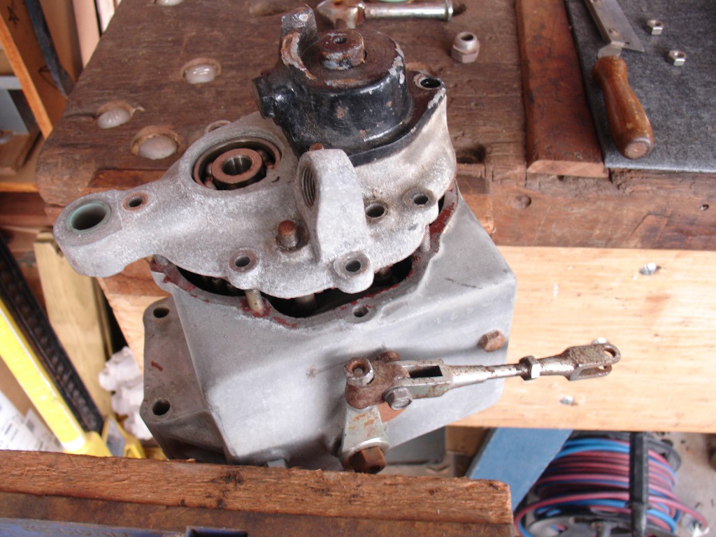
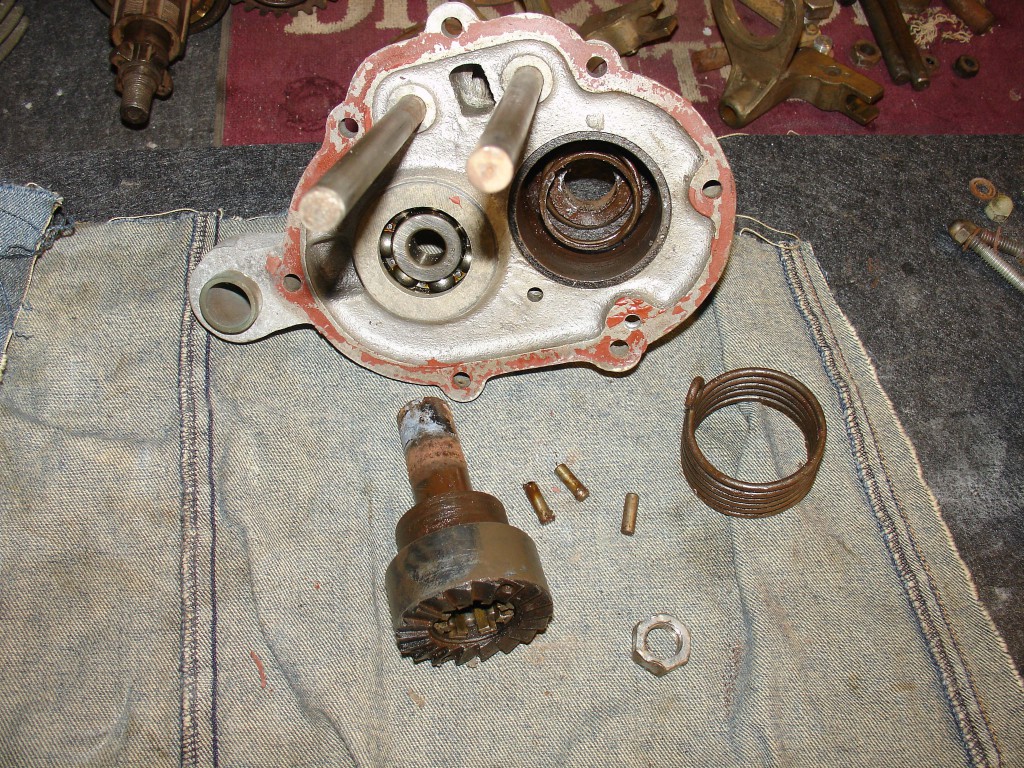
Not for long, though! I shouldn’t get so cocky, I forgot my procedures…So, I go to take the COVER off first, forgetting to push the kickstarter-ratchet through the kickstarter-spring-and-ratchet-housing-thingy (‘Kick Starter Bearing’, BK-4, plate 5!), having forgotten that THIS gearbox actually has a spring in there, unlike the last one. My mistake, gently press the ratchet into the box while continuing to gently remove the cover. No dramas here and once that was off and the spring removed from the kick-starter ratchet itself, the cover could come off, too, without the ratchet hanging onto the rest of the gearbox. Same procedure for removal of the internals here as before, not forgetting that the kickstarter has rollers and pins to fall inside, so if there happens to be any oil in there, don’t forget to count the bits as they are removed and to recover any missing bits BEFORE tipping the contents anywhere that would make it difficult to locate small parts after the event!
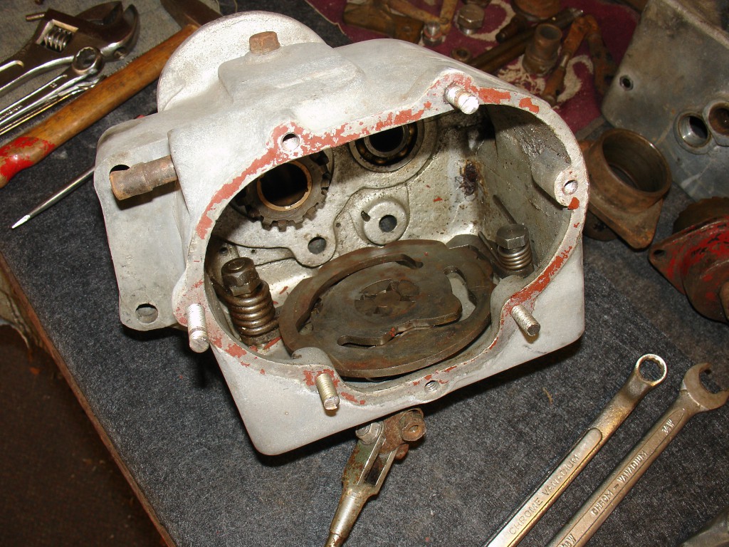
Inside looks a lot cleaner, not much surface rust on the steel parts, if any. Interesting is the cam-plate, which is the same way up as the 10-prefix box (or vice-versa). The postwar boxes often had the one-down-three-up configuration to comply with (originally) WD wishes, as they wanted all WD bikes to be the same…Luckily for us, the Velocette quadrants were all reversible, simply by taking them off their centre and turning them around…I do prefer the one-up and three-down for myself, I must admit, though potentially fraught with danger for box and rider if uninitiated (or only ever ridden bikes with left-foot-gear-change)
My theory is that it is more natural to twist the throttle towards you (as in open or ‘blip’ the throttle) and move your toe upwards (also ‘towards’ you) at the same time when changing to a lower gear (and vice-versa, relaxing the throttle while pressing the gear-lever gently down for an ‘up’ change) Than doing it the other way ‘round (Anyone out there think of a better excuse – sorry, ahem, ‘reason’ or ‘explanation’, I meant, of course – to back up my theory?)
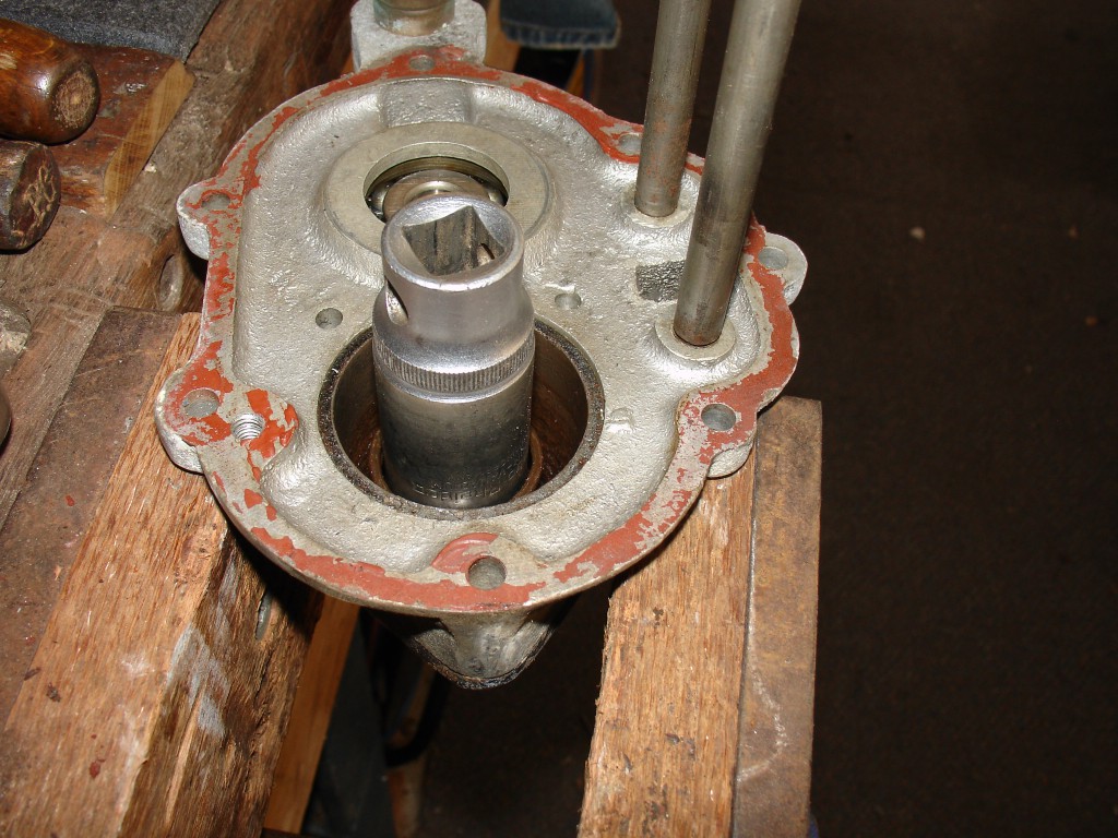
The rollers supporting the end of the layshaft are still in the ratchet (and can’t really be seen that well from this angle), the pins and springs are, nonetheless, clearly visible. The housing is pretty tight on the front cover. To remove it is easy…I use an old, very solid spark-plug-socket, which fits nicely inside and use of the nylon or ‘dead’ mallet/hammer, thus, and, of course, my trusty carpenter’s vice, Thus:
…being careful to give the cover maximum surface to rest on, so nothing gets broken or cracked!
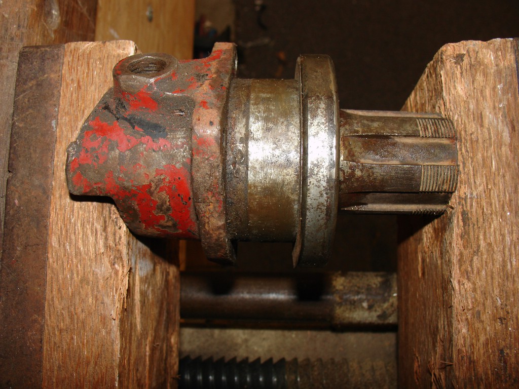
A different problem is posed by the bearing on the main-shaft, which in this case was reluctant to come off the gear… Then I looked at BK-4 in a different light, tried it out and see there, it fit perfectly! Here is an obvious foresight of the excellent Veloce engineers and the factory gearbox-drive-side-bearing-removal-tool was put to the use that it was actually designed for!
Once your eyes have realised that the ramp on the left is actually resting on the TOP of the wood of the vice (pictured from above), it becomes easier to interpret what is going on here: The cut gears of the BK8 Sleeve-Gear (17T Standard ratio, as are both gearbox-internals) are pushed INSIDE the kickstarter-hous… damnit, BK-4 and the base of the latter rests nicely on the bearing, the gears inside have about 3/4” clearance (i.e.movement) to the inside of the housing. Press these between the wooden jaws and…nothing happens! Press HARD and still nothing happens. A squirt of RP7/WD40 around the bearing-base and a few taps with the nylon mallet and BINGO! The bearing moves the increment that the vice was under tension and the process can either be repeated until the gears reach the end of their movement or, if it’s not that stubborn anymore, simply wind the vice-handle and the bearing will be pushed off the sleeve enough to take it off by hand. Voila!
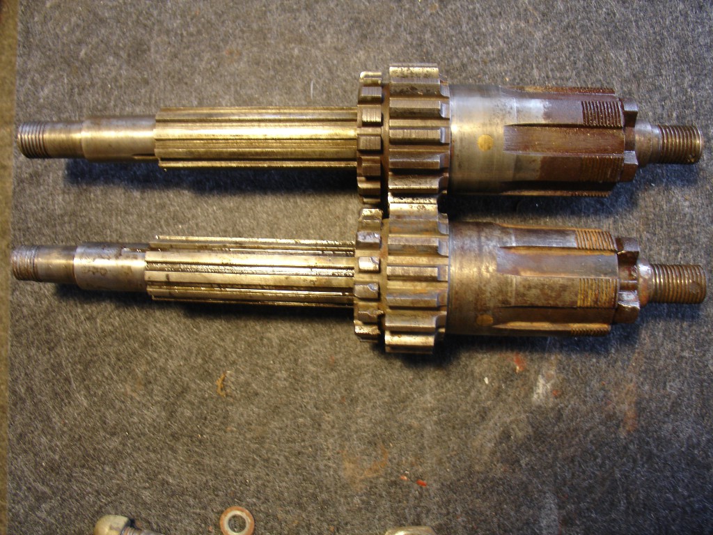
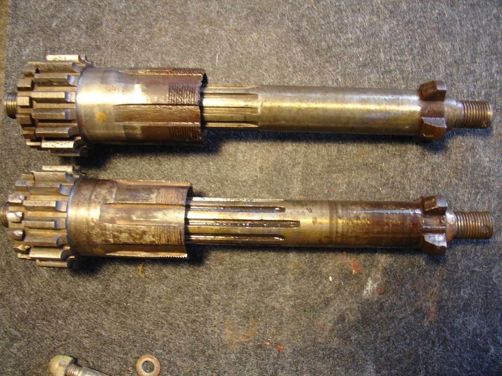
Interesting is the comparison between the two main-shafts and their sleeve-gears. The sleeves are different lengths, have a different angle recess on the ends and the bearings are of different lengths, ‘hooding’ the end of the shaft of the earlier box more than the later one. Even more interesting is the difference in the length of the splines on the main-shafts as shown below…any explanation for that one? I would be curious!
One last thing of interest to me was the direct comparison between both cam-plates…The later one had the same slots, same width, but much smooother contours than the early one, where the transition between the curves was much ‘sharper’. Very subtle change that would have made a great deal of difference to the ‘feel’ of the gear-change, and the amount of ‘clunk’ between changes, too!
©peter gouws 2012
