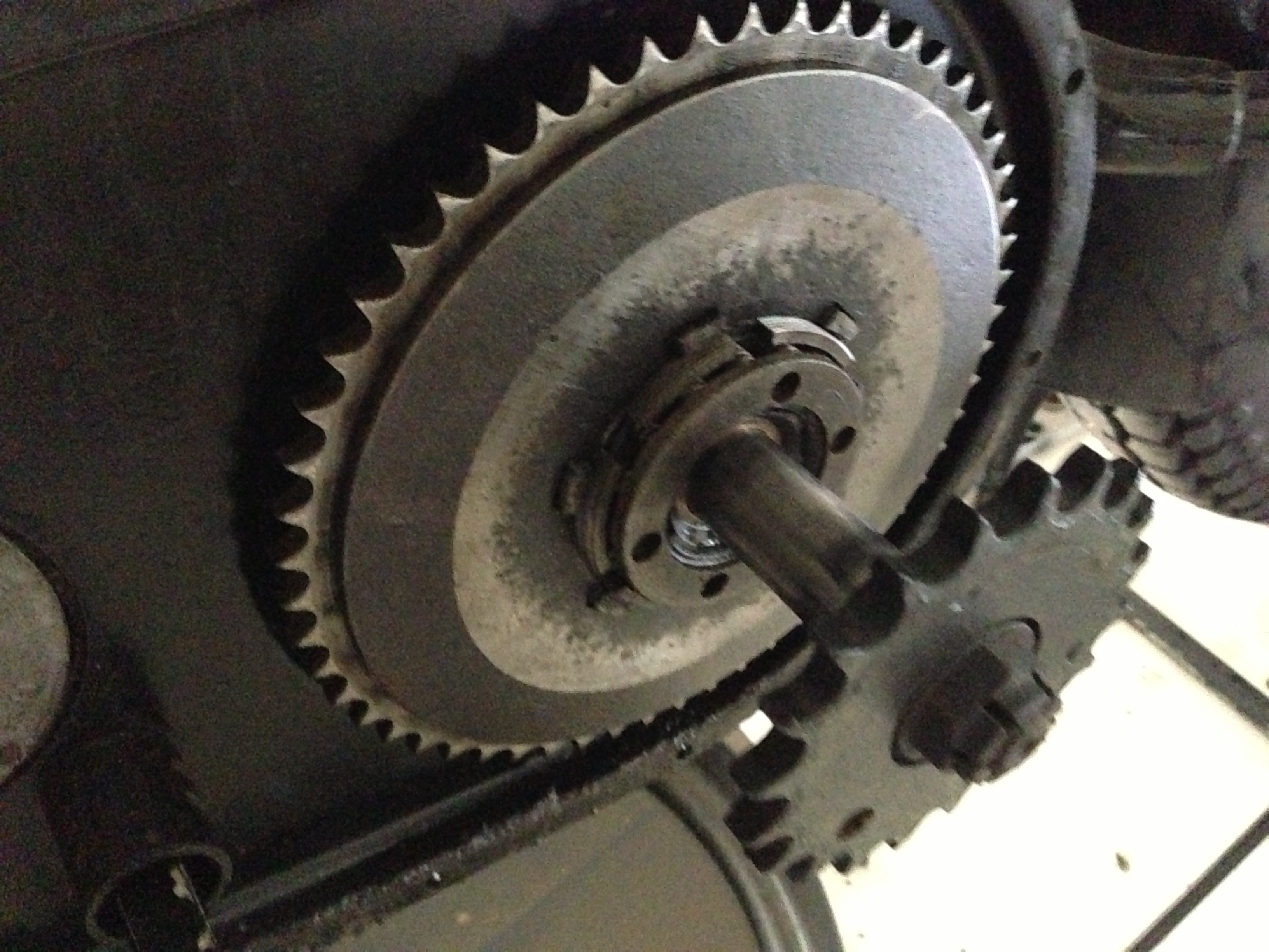
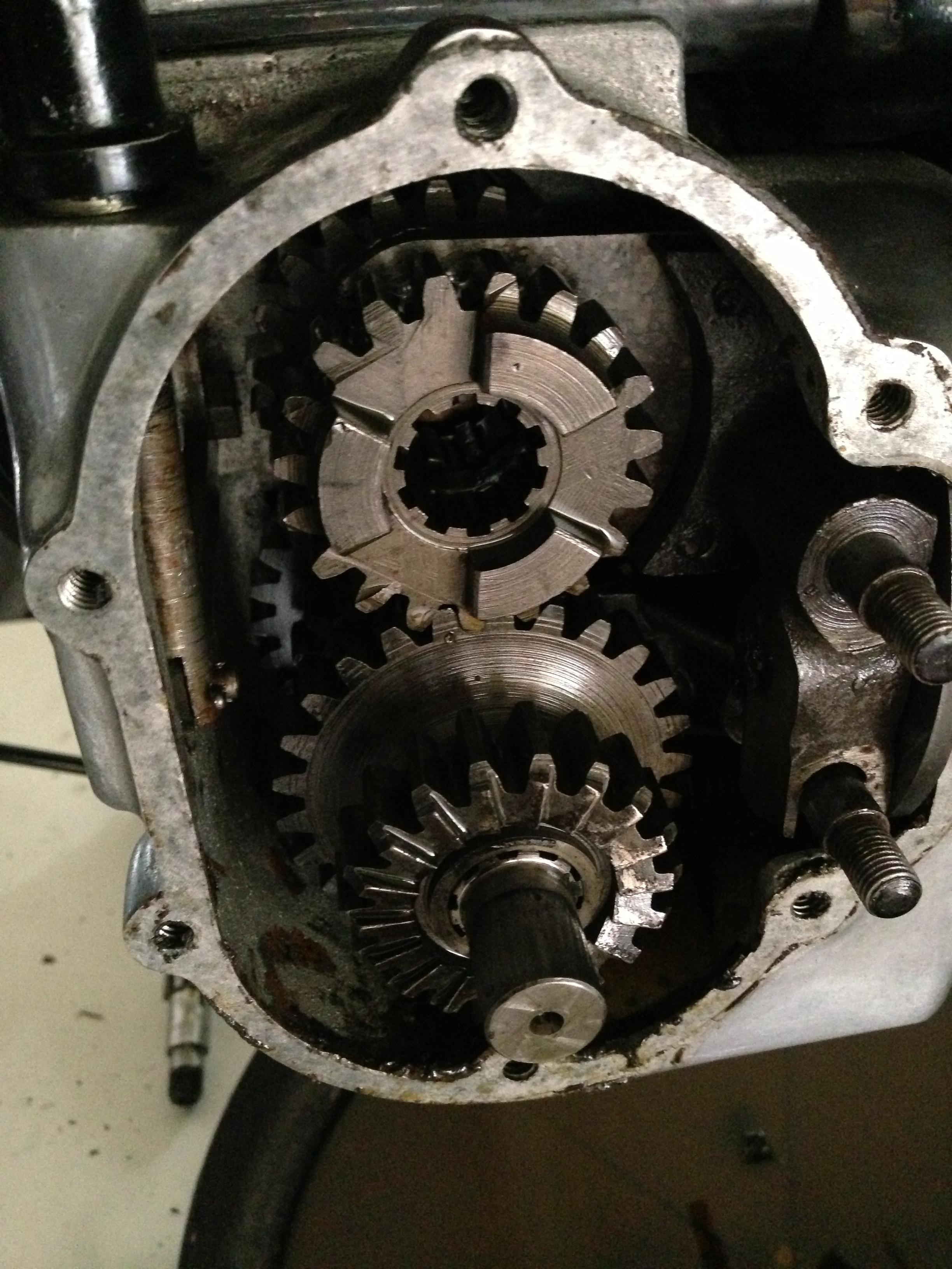
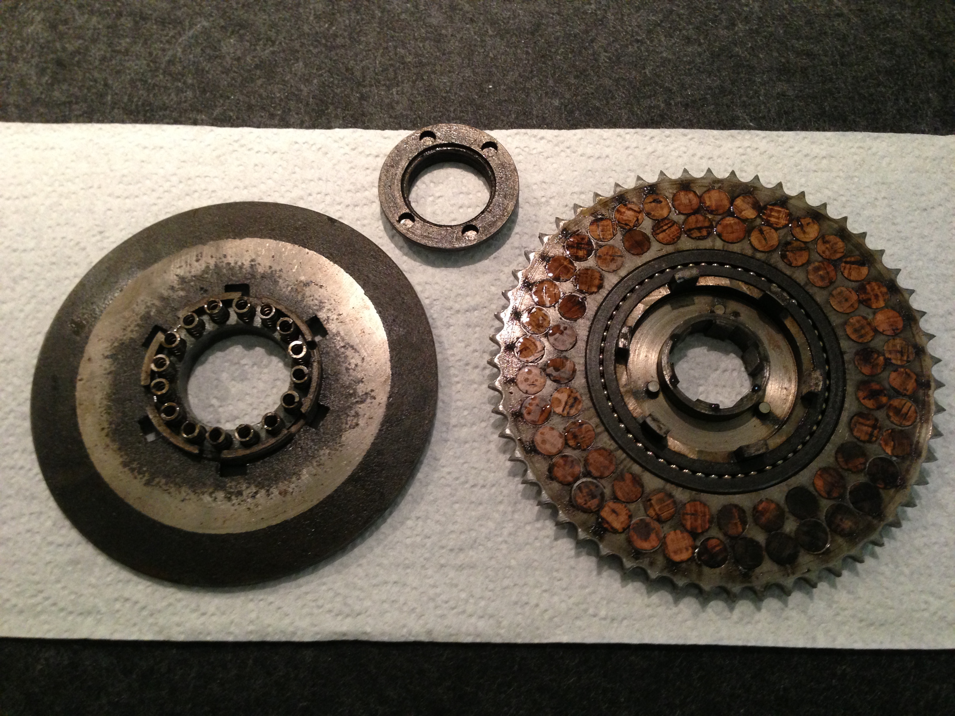
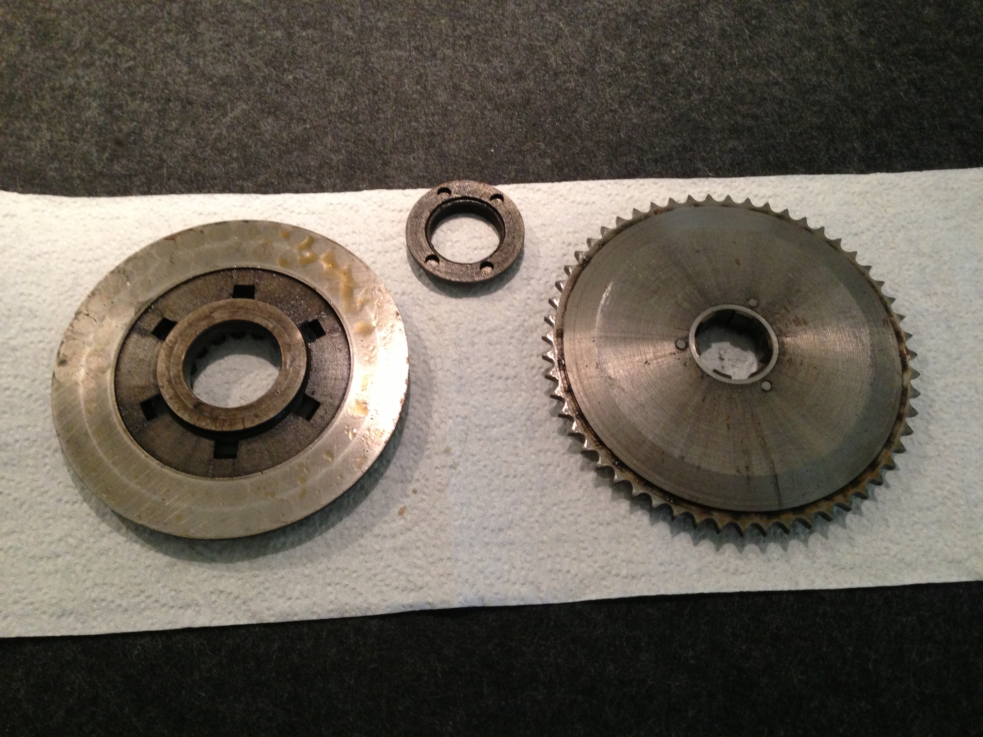
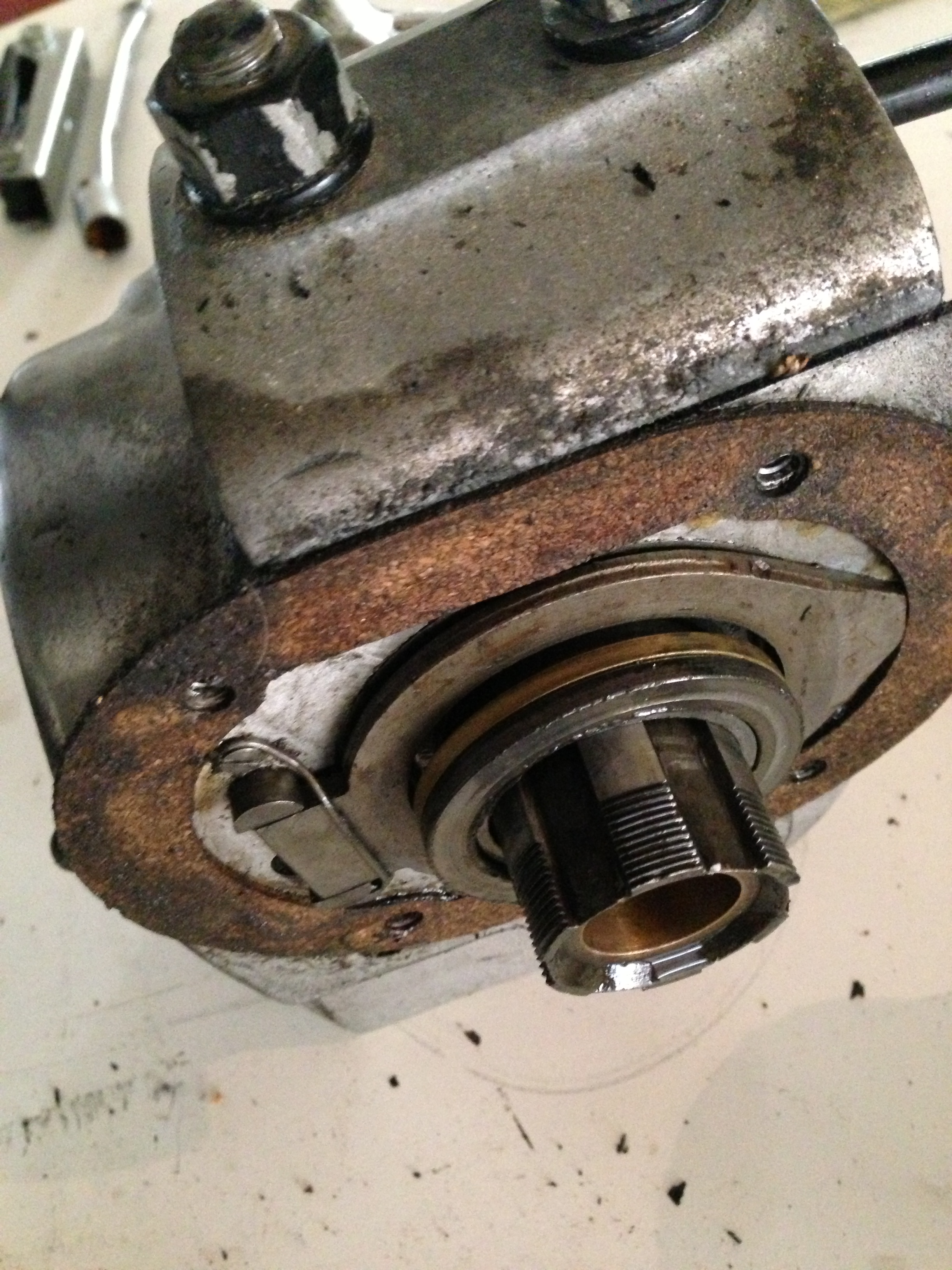
It is certainly not every day that anyone gets the chance to have a look at and dismantle a Velocette single-plate clutch, as fitted to the pre-war MOVs and the GTP series of bikes, so I thought that while I’m at it, I could take a few pictures and document what it looks like and how it goes together… one never knows when it might be of use to someone. It is often said that most Velocette gearbox problems are actually clutch problems, but looking at this, there is actually very little to cause any problems at all. Altogether a wonderful setup, and the sturdiest little clutch I’ve ever had the pleasure to work on or with. Talk about robust! No plates to warp here, that’s for sure. The simplicity of the design is genial and it is no wonder that Veloce continued with this setup right until the end – albeit with a few changes along the way, as a result of what I believe is called ‘progress’.
Above is the bare clutch, with the mainshaft about to be removed…
… as shown above with it already out, from the ‘other end’ of the gearbox.
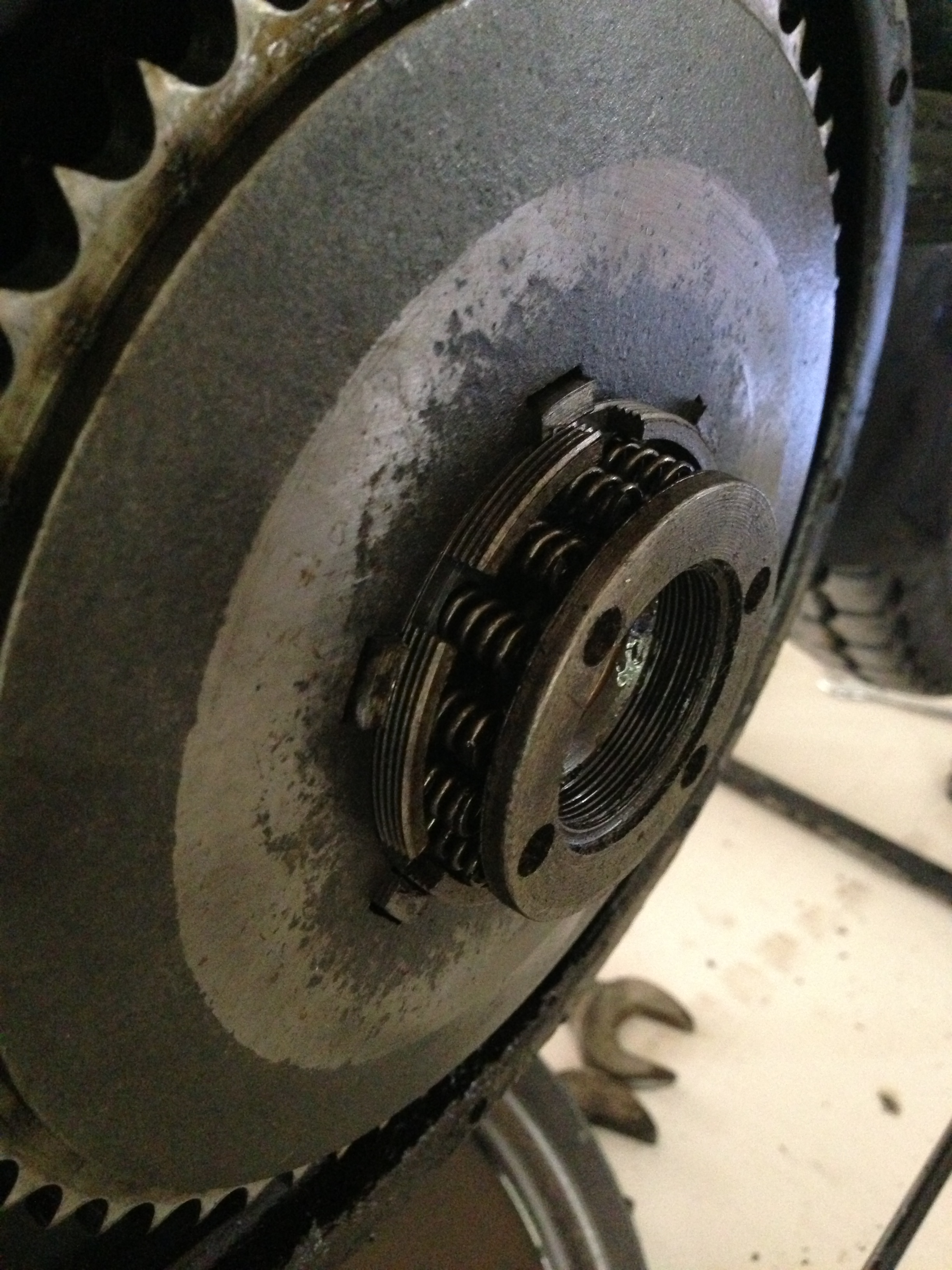
The spring-ring is undone with A61/2, a peg-spanner, which you either have or have to improvise. Do NOT hammer it undone with a screwdriver in one of the holes, PLEASE! Here it is shown almost about to fall off
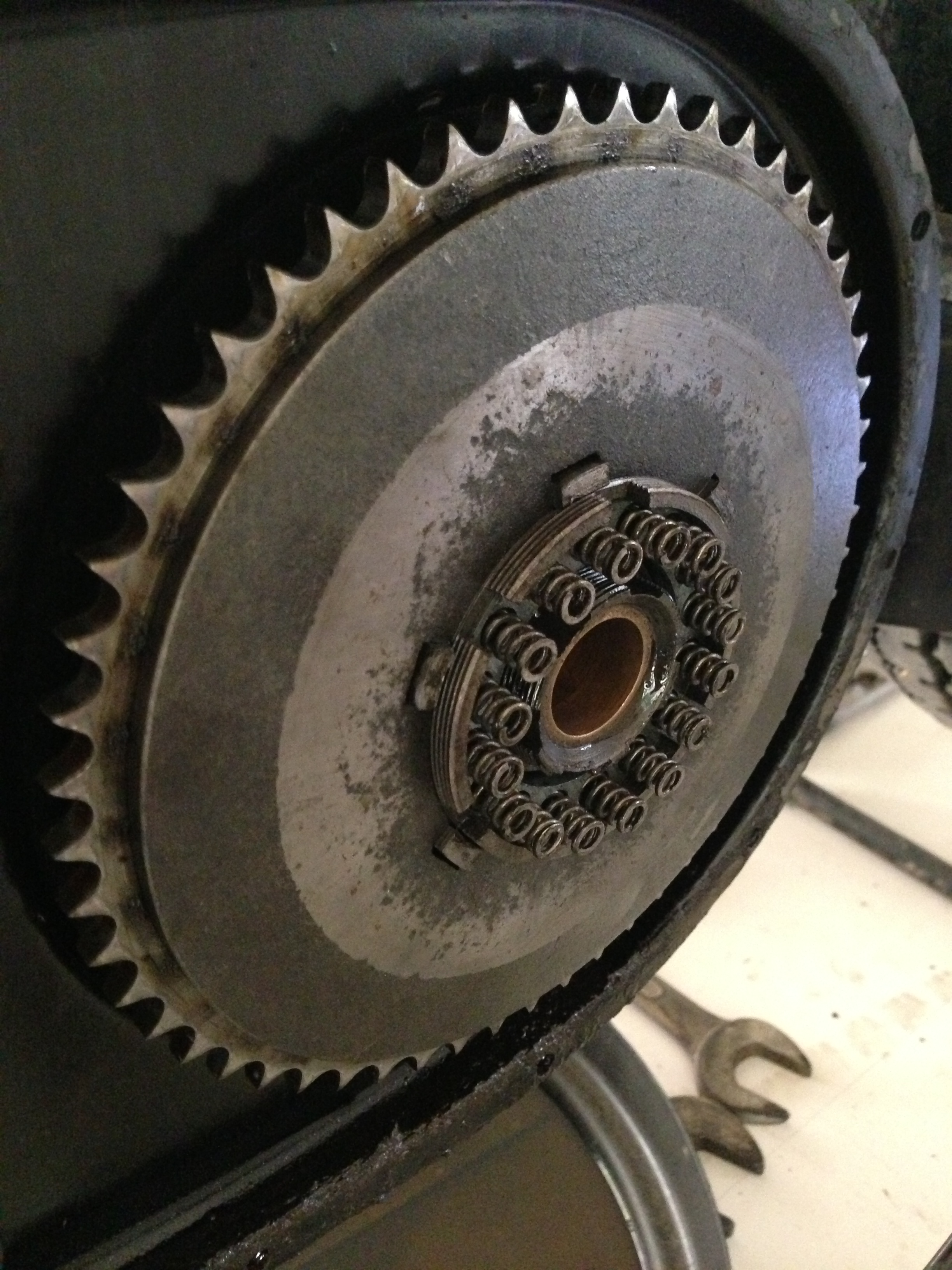
and here is the ring of sixteen springs hidden behind it, which do all the work (Thruxtons have 20 springs)! Unlike the later restrictions in the availability of larger-diameter spring-wire after the war, which led to designs like the Vincent’s clutch on the series B etc, this was actually designed like this ‘on purpose’ a LONG, long time before WWII… I wonder where Uncle Phil got his idea from…?
So here on the left is the solid front plate removed With the collar and springs still attached and on the right, the plate behind it with the cork friction-material, the bearing-ring and the three actuating pins in the depression around the central boss.
This is what they look like from the ‘other side’. The working of the clutch itself is probably the most talked aspect of Velocettes the world over… and I see no need for further dis-assembly at this stage. Maybe later?
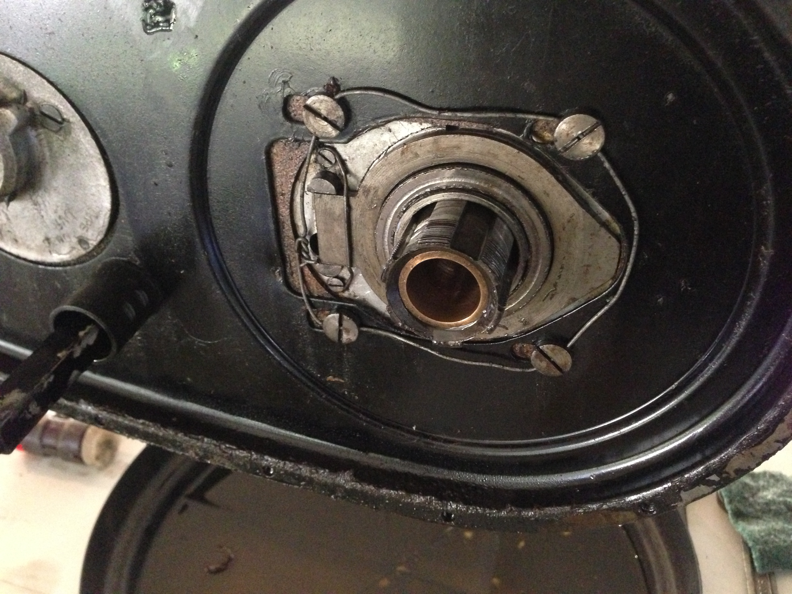
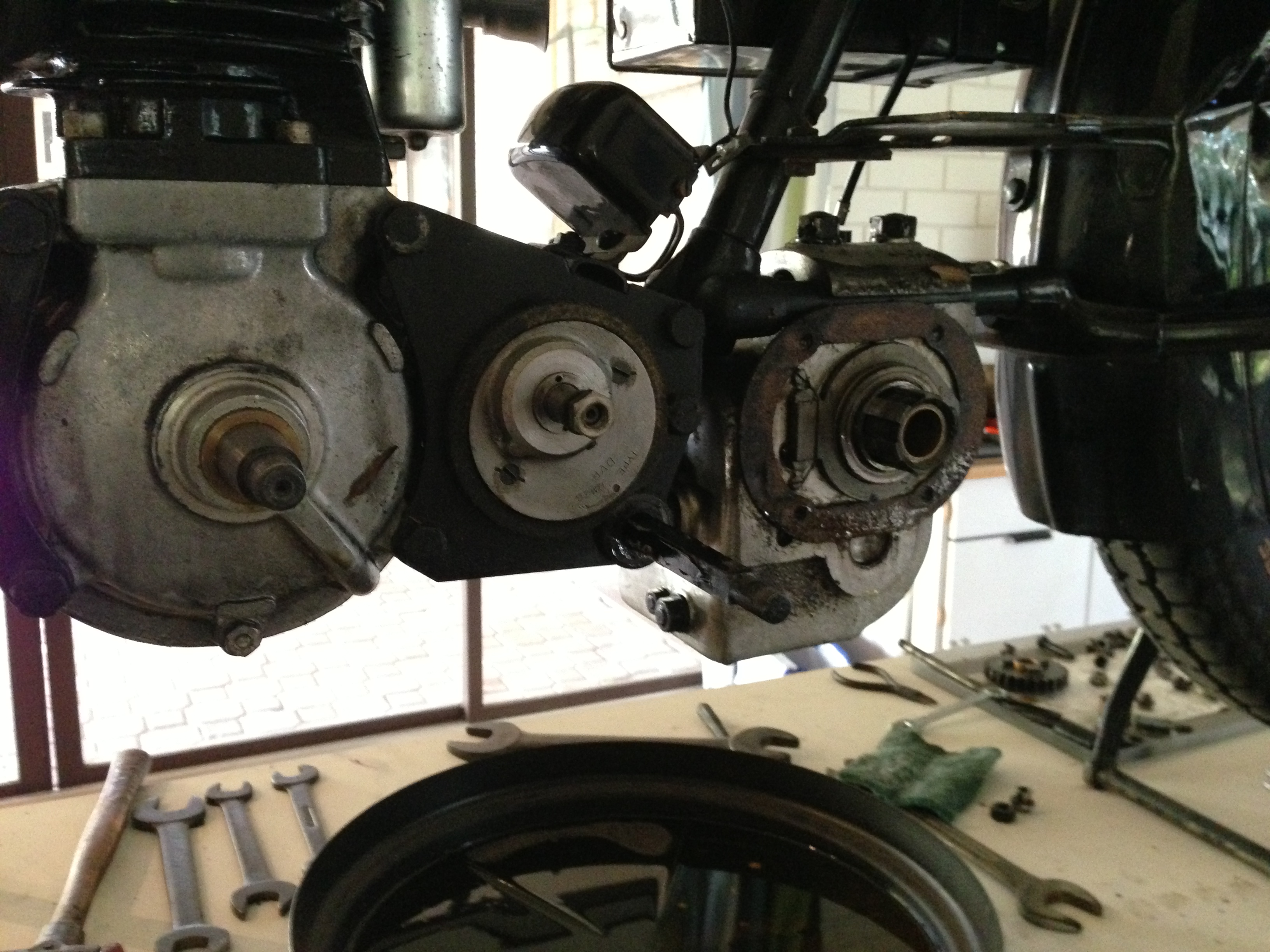
Now that the clutch is off, the screws mounting the chainguard and the clutch actuating ‘ring’ are revealed On the left of the protruding gear (also wired on) is the fulcrum of the ring.When the clutch lever is pulled, this end of the ring is pushed off the flat back towards us (as in ‘outboard’) from behind the tab on the right, basically ‘skewing’ it and therefore separating the driven and driven plate(s) from contact with one another…. The chaincase retaining-screws have been wired to stop them inadvertently rotating and undoing, a somewhat embarrassing and expensive, if not dangerous experience, I could imagine…
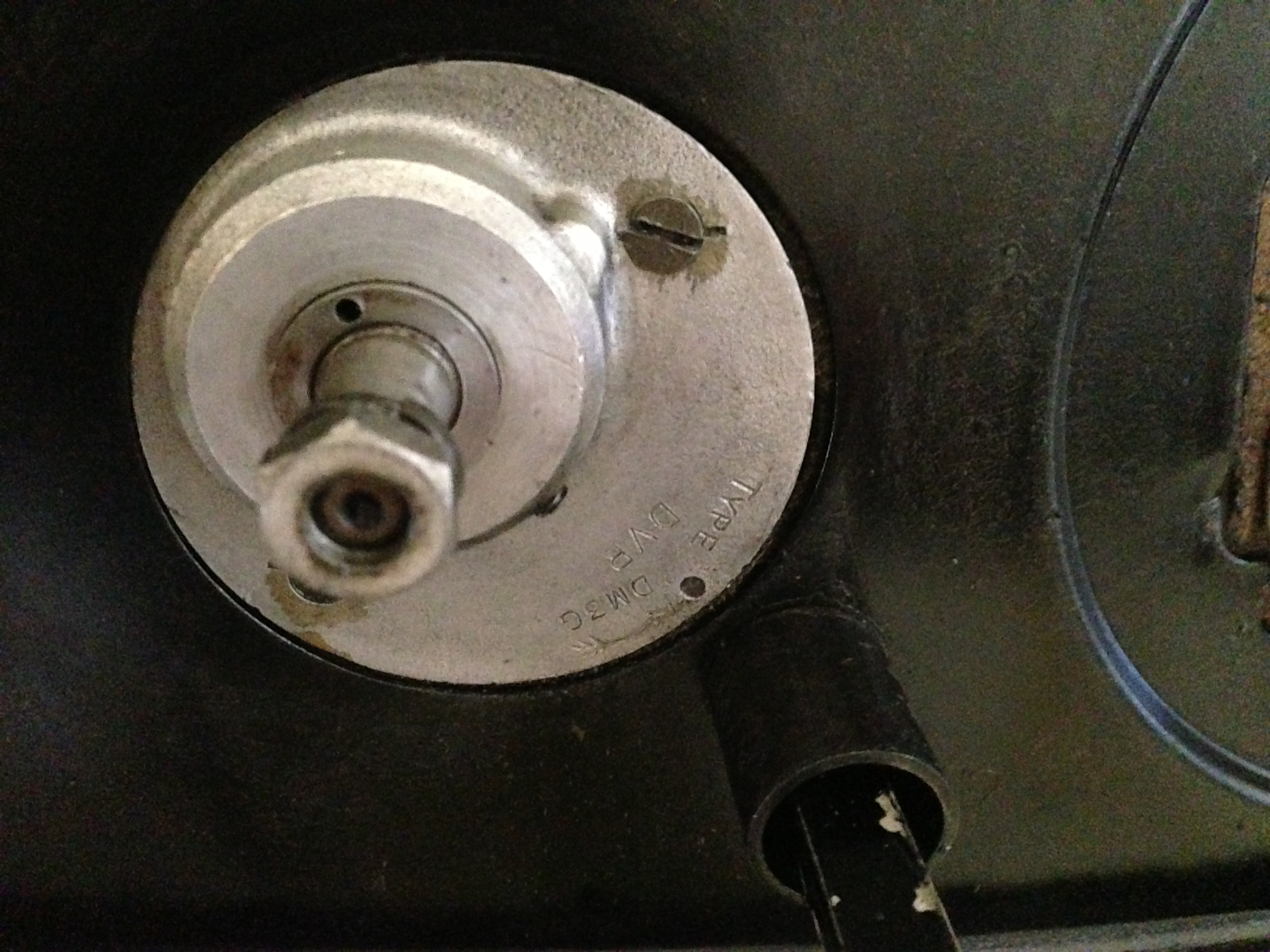
Just for reference, the ‘business end’ of the dynamo, without the pulley, which on the GTP sits IN-side the Primary Chaincase
Here just a view of the whole plot with the chaincase removed, showing just how minimalistic everything is. Veloce went to great lengths do devise a very stiff and light setup to the whole machine.
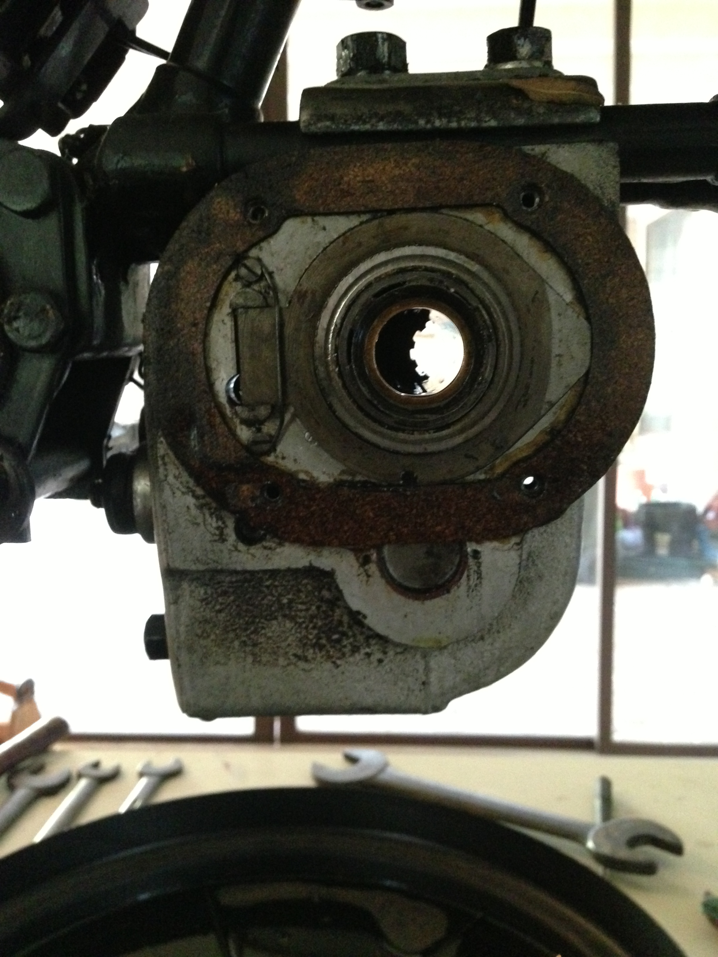
Looky-looky through the hole left by the shaft and showing the gear on the other side which has toppled to the right. Obvious here is also the road-grunge and dirt that this machine accumulates. Not a bike that sits languishing in a posh living-room on a stand, believe me! This machine does some serious touring, with dents on the mudguard at the front where the Webb forks bottom out over railway-lines at speed… (unintentional, but nevertheless there…)
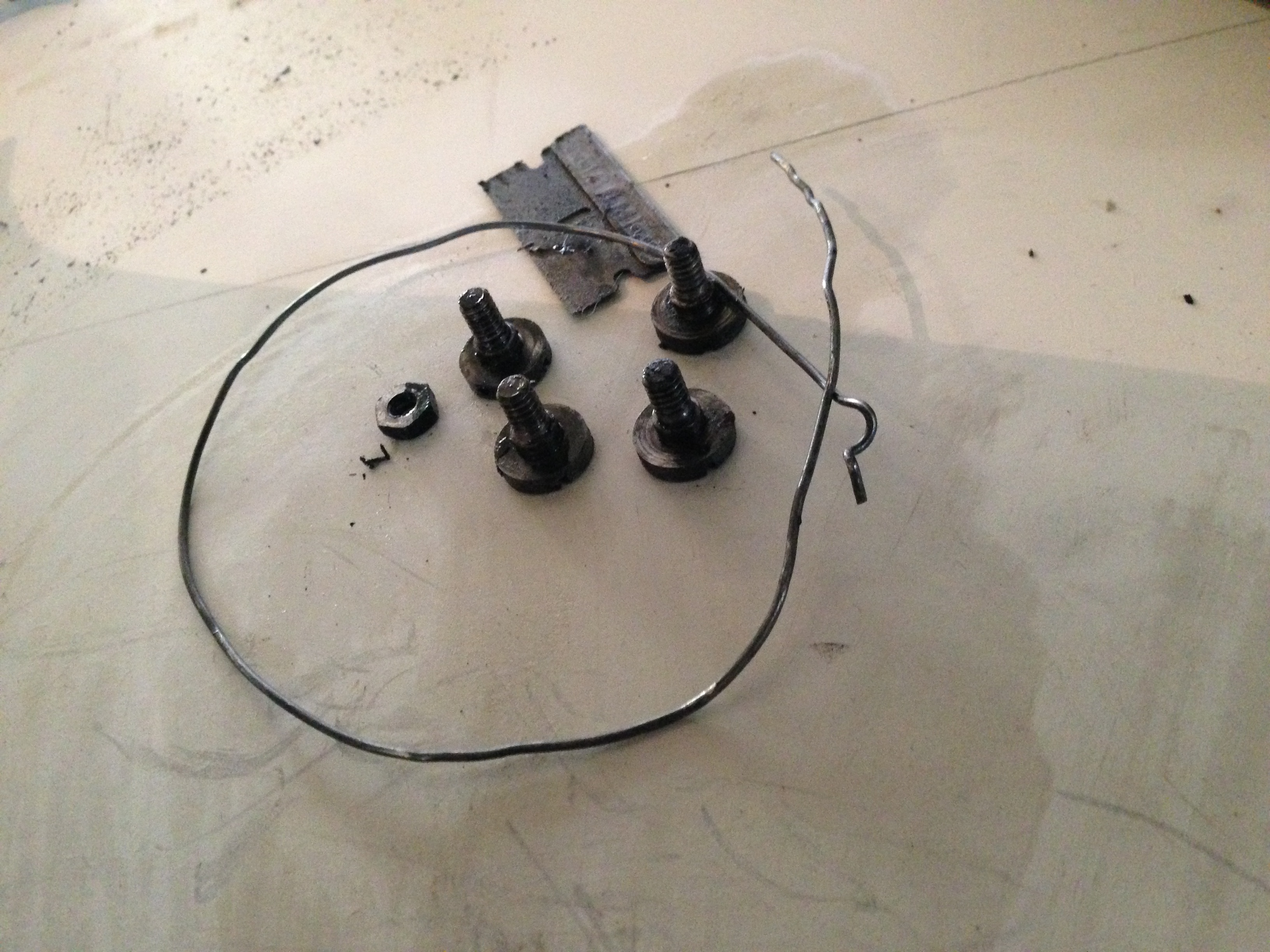
Interesting. these are the four screws and the fencing wire and an extra nut off the chaincase inner (the nut held the pillar that the dynamo-pulley-guard screws on to on the perimeter of the chaincase. I hadn’t noticed at first until it fell, but while looking and preparing to take a photo, a movement caught my eye… something had fallen off! And here it is with the other bits: A ‘hobby’ razor-blade… I’ll have to ask Pud about that, it might just have been the right thickness to stop something rattling… Who knows!!
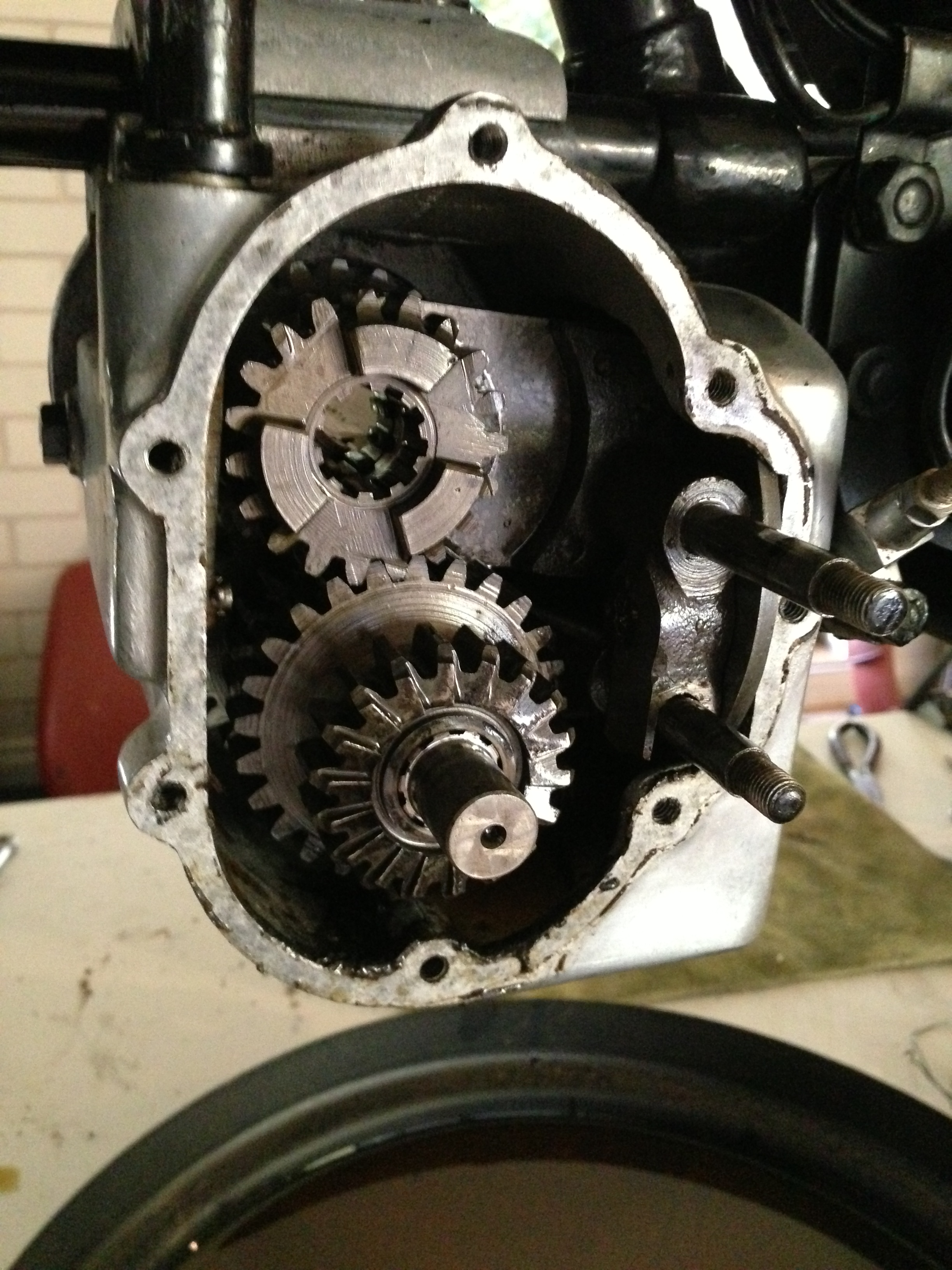
Well, now the guard is off the other side, I can ‘drift’ the pins out that hold the selector-mechanism in place, for ‘ease’ of further dismantling. Those are them on the right of the picture, sticking out of the innards, not yet completely removed.
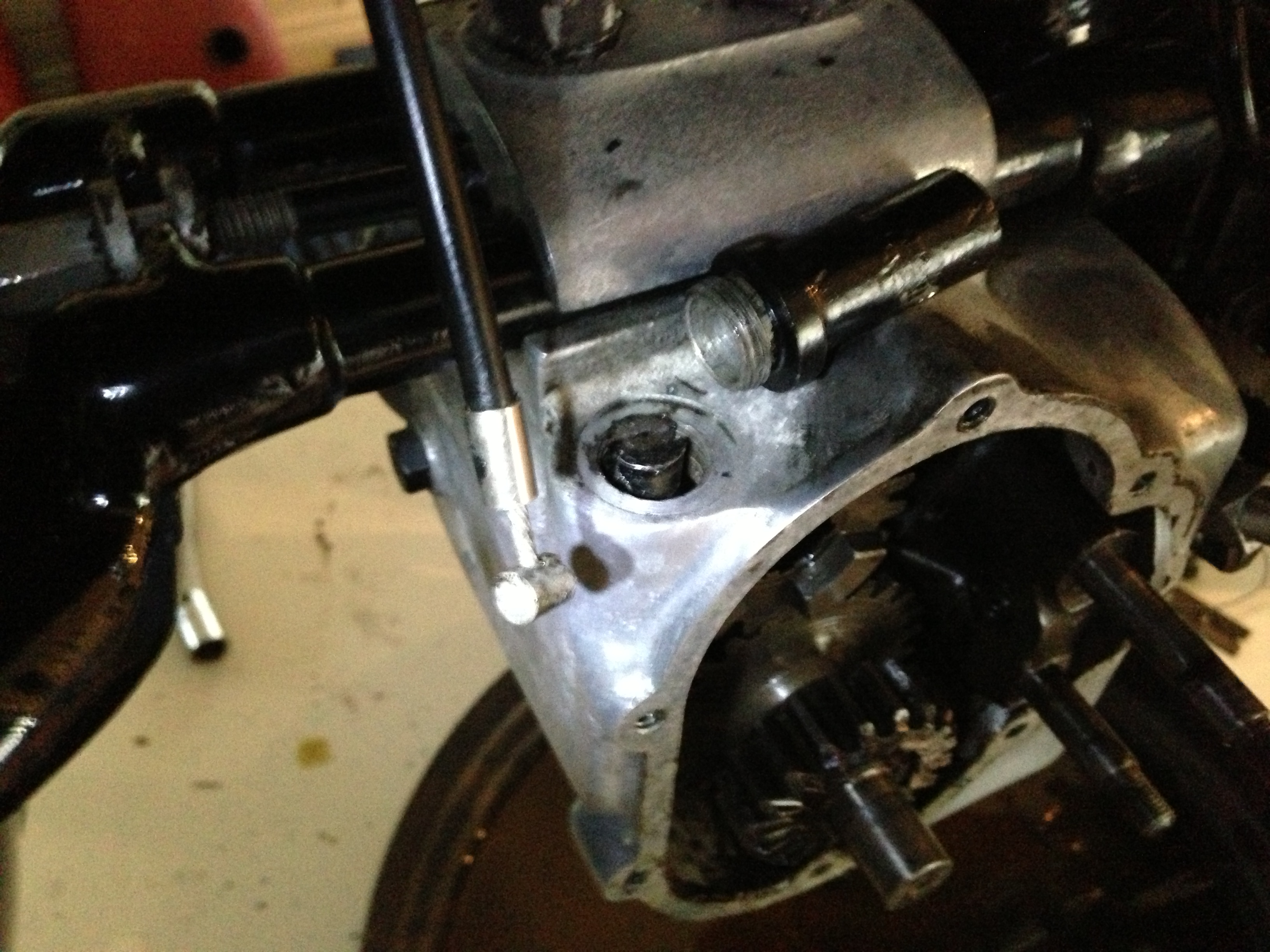
And a shot of the clutch actuating cable, having removed it from the lever in the box (in the ‘ole), after unscrewing the tower (the black tube lying on the top of the box) it normally hides in. This is actually the only weakness with all the Velo boxes of this era, as the tube offers an opportunity for water to enter the gearbox at this point. Water drips down the cable when riding in the wet and goes in through this hole. The remedy is the type of grommet-thingy also found on handlebar-levers and the tops of carburettors. This one’s grommet was dried and cracked and probably the reason for the small amount of whitish-goo in the gearbox. More of that on further inspection!!
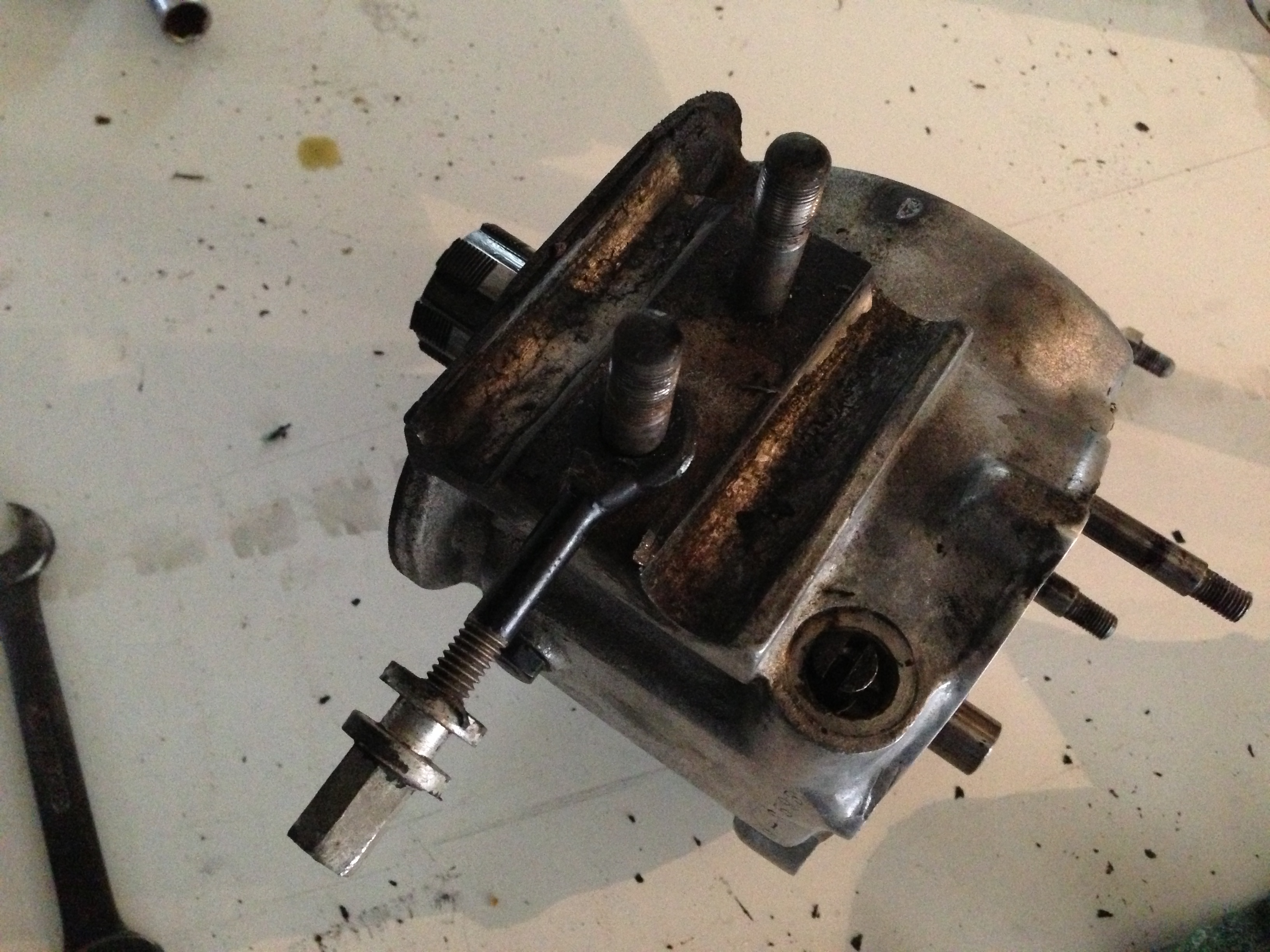
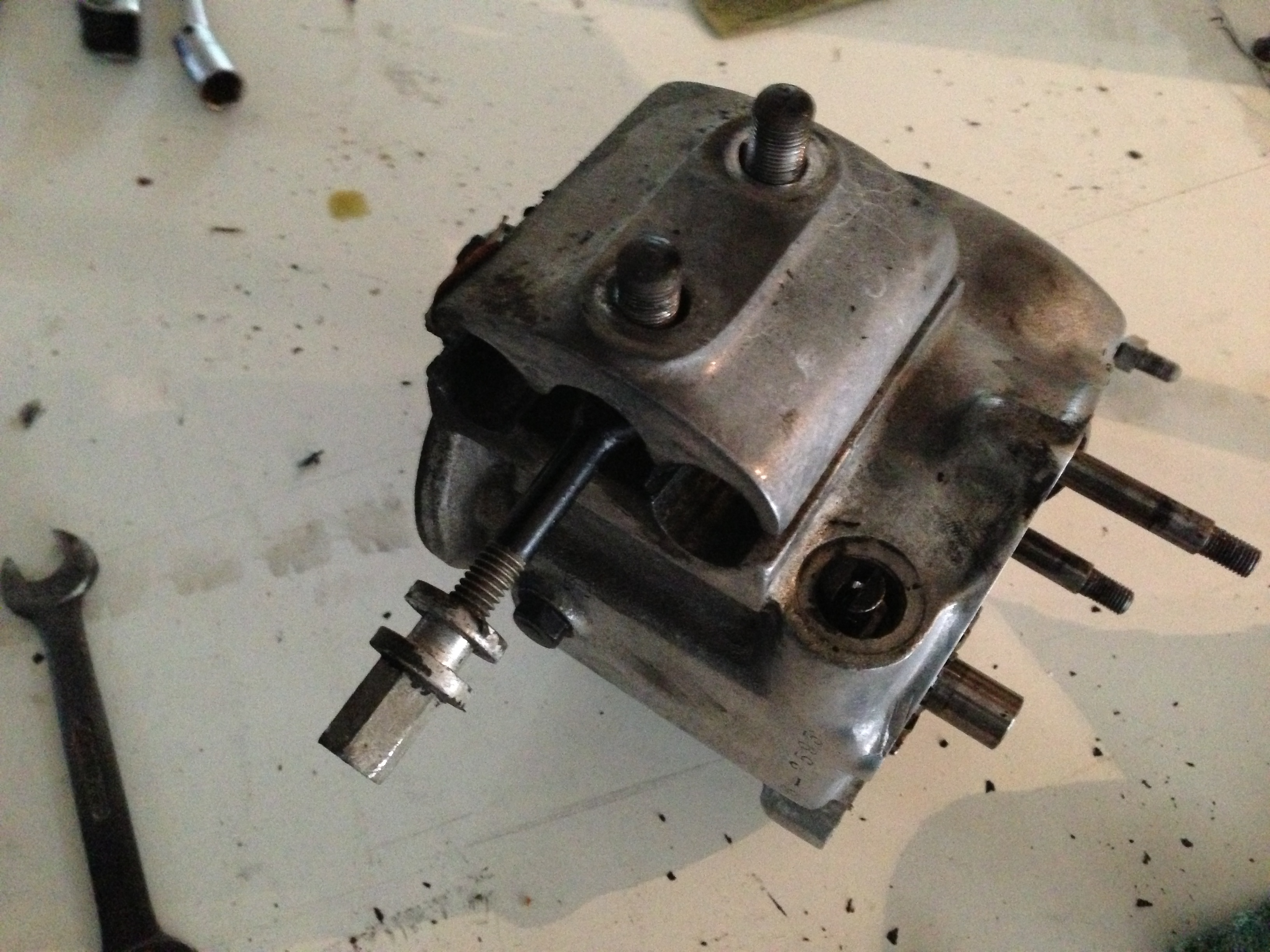
Just for reference, this is the way that the gearbox mounts on two rails on the frame, the screw is used to adjusts the chain-tension and fits on an appropriately shaped part of the frame just forward of the rear mudguard.
The clamp on the top of the ‘box…
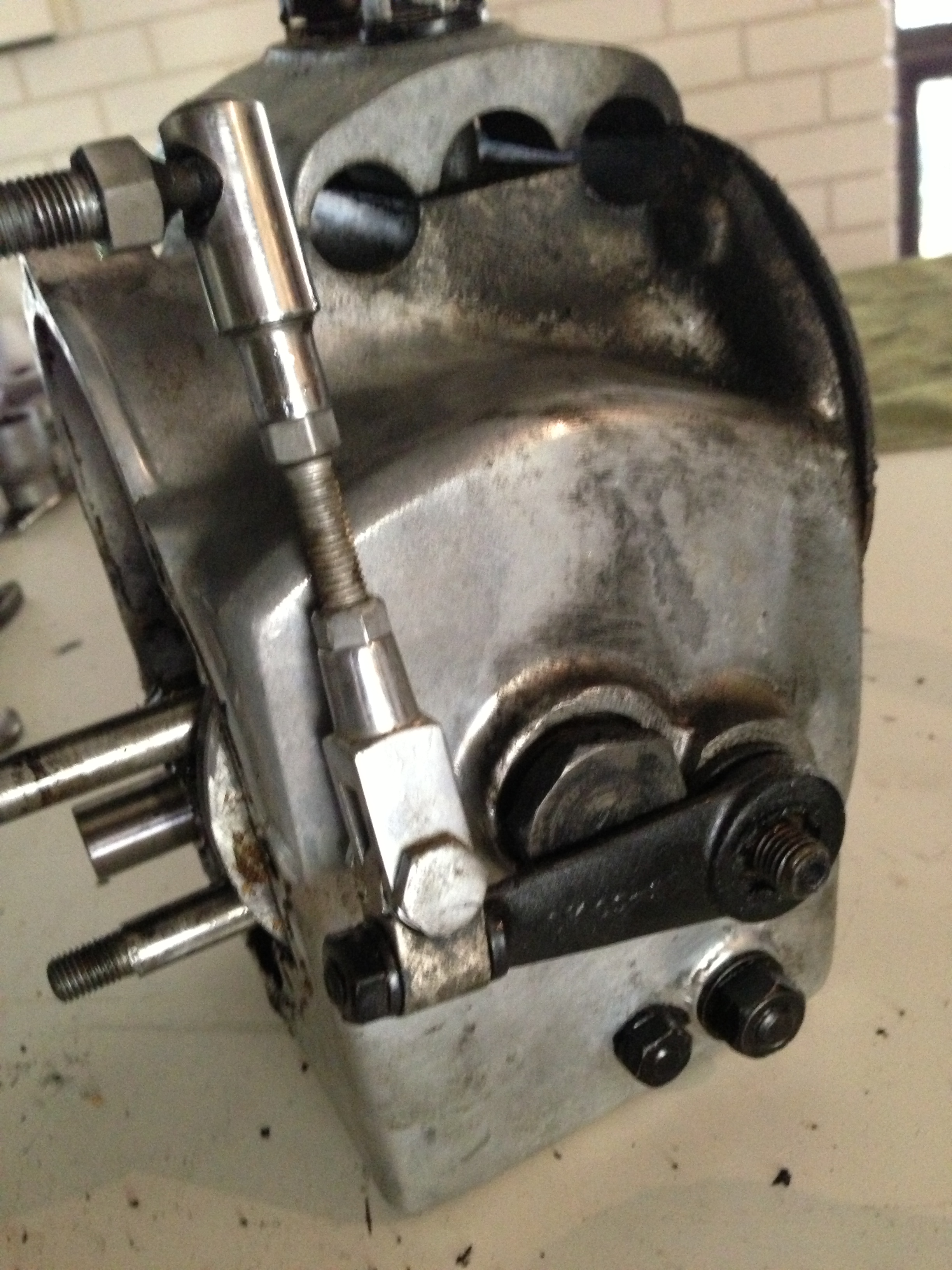
…and here the gear-change leverage on the outside (front-facing) part of the gearbox, very difficult to get at and impossible to remove in situ, which is why I took the trouble to take it all out in the first place!
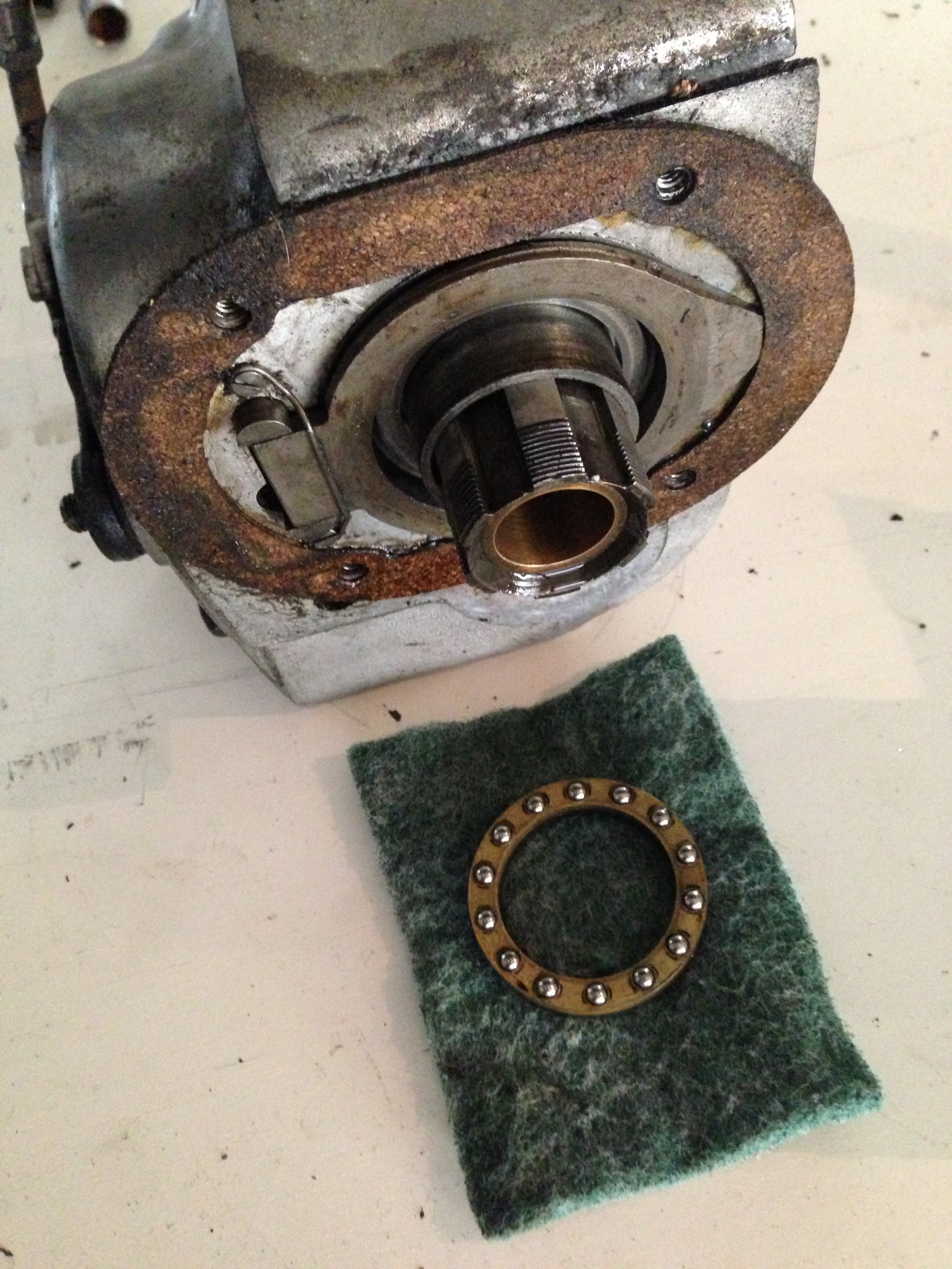
Before going any further, I just want to secure the thrust bearing inboard of the clutch before removing the sleeve-gear and everything else… here it just looking out of the gearbox casting and below, removed and place in safety somewhere that I can keep it clean and find it later for re-assembly (yes, the inside ring is still not out, I know… that’s still sitting on the sleeve-gear!
Well, that’s it for for Doctor Peter’s clinic today, folks! Hope you enjoyed today’s episode! More coming soon on the same channel, stay tuned!!
© peter gouws 2013
